|
|
Background Aquarium owners already know the benefits in having a CO2 system. With a CO2 system, the water will maintain a stable pH-value and the plants will grow much better. The water quality and pH-level are important when it comes to shrimps, and especially when breeding shrimps. A simple solution, to achieve a stable eco system, is through using a CO2 regulating system. Most of the CO2 systems are complex, expensive, hard to calibrate and they do not regulate CO2 in an efficient manner. After extensive research of existing CO2 regulating systems and testing them, we finally decided to design our own system, geared specifically towards aquarium breeding. This page will provide step by step instructions on how a CO2 system keeps a stable eco system in your aquarium. Through using our newly developed system our aquarium plants are flourishing and our fish and shrimp breeding is thriving. The use of our system improved our own aquarium eco-systems to a substantial degree.  Carbon regulator - Controlling Device
The best way to keep carbonic acid levels (and pH levels) stable is to have an automated dosage system of CO2 gas. With an automated system you will not need bubble counters or have to consider the amount of gas you inject into your aquarium. The Carbon Regulator handles it all. The image on the right displays the components of the system. Overview : A pH-value probe (1) is placed in the aquarium and it generates an electric signal. The controlling device (2) measures the pH-value continuously and regulates an electrically controlled gas valve (3). When the valve is opened the CO2 gas will pass through and finally dissolve in the water through the diffuser (4). The CO2 gas will influence and change the pH-value in the water. When the "user required" pH-value is reached, the valve will close and cut off the gas flow to the diffuser. The CO2 gas can come from many different sources. Some use gas tanks, others use a yeasting process. You can read more by following this link.  pH Probe (1) :
The pH probe (1) is placed in the aquarium and it measures the pH-value. The pH level is measured through the pH probe sensor. The pH sensor, located in the water, will generate an electrical signal proportional to the pH level in the water. Controlling device (2) : The controlling device is the heart of the system. The controlling device consists of a circuit board with two LED displays and three buttons. The display shows the pH-value and the buttons are used to obtain required settings. The system is very simple to learn. It takes a new user less than 5 minutes to fully comprehend and operate the unit. Simplicity is our main goal! Behind the simple user interface are two complex micro computers. 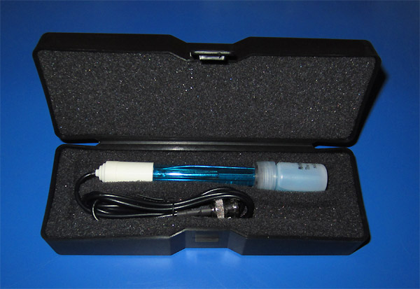 They measure the "actual" pH-value in the aquarium and analyse if an injection of CO2 is required.
A unique feature, with this control board, is that the processors consider several parameters before deciding if an injection of gas is required. Every second, thousands of decisions are being made. We want the regulating system to be stable and inject only as much CO2 gas as is required to keep pH level stable in the aquarium; no matter size of aquarium. By using an intelligent software system the control board keeps the pH level stable. The pH is stable even when the environment changes from day to night, and when air pump or circulation is turned on and off. The pH-value is always stable. Why using two processors? (Aviation Computer Security) One processor is always working constantly. If it stops working for some reason the second (backup) processor takes over the work. For example: If the main processor would software freeze due to power variance, the other processor will take over the work and make sure the system is running. The frozen processor will restart itself and after a few seconds everything returns to normal. A software freezing can occur due to power glitches or power spikes on the main power line. This does not happen often, but IF it does happen we do not want a frozen system. This safety feature is common in aviation security, but is rarely found in carbon systems. We find this back up system to be essential for smooth running of a Carbon Regulator System. So what does the display show and the buttons do? You have three buttons labelled "pH Show", "pH up", "pH down". When "pH show" button is pushed, the LED display will show the actual pH-value in the aquarium. The pH-value is displayed in one decimal form e.g. "6.6". Further decimalization is computed but is not required for the display. The buttons "pH up" and "pH down" are used to set the "user required" pH-value in the aquarium. When button "pH up" is pushed the "user required" value is shown in the display and the regulator will adjust the environment in the aquarium. The same applies for the "pH down" button. Electrical vale for CO2 gas (3) :  The valve consist of a solenoid. When power is applied, the magnetic field moves the solenoid and the valve opens.
The controlling device is connected to an electrical controlled gas valve (3) with two wires (plus and minus). The picture at right show a polarised valve. Click the picture to see larger photo. The valve has 6 mm quick connectors for input and output. The valve has 6 mm quick connectors as input and output. The valve we supply has a pre mounted plug on its cable, matching this output - just Plug & Play. The controlling device regulates the gas valve, which will inject CO2 into the aquarium. Any valve can be used with this carbon regulator as long as the valve is made for 12V. (We have a module to control 110 and 230 V valve as well, please contact us for more information.) During an hour the Carbon regulator can open the vale up to forty times. Each time the valve can stay open for max seven seconds. Click at the picture at right to see the valve in large picture format. 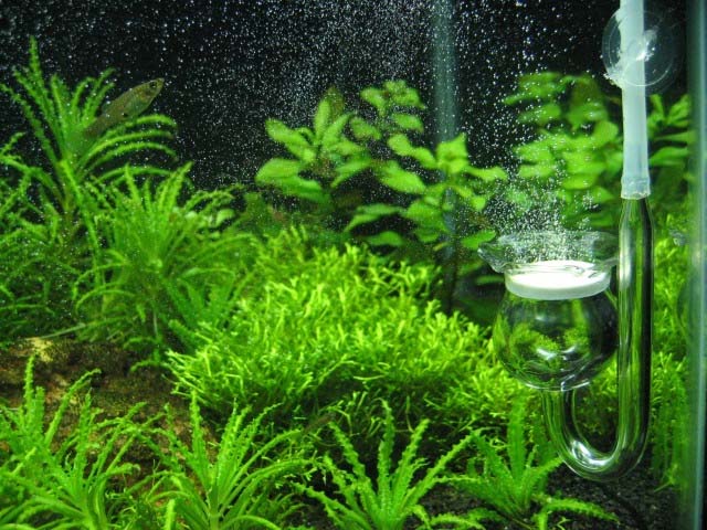 Diffuser (4) :
The Diffuser is placed in the aquarium and the purpose of a Diffuser is to create very small bubbles of CO2. The small bubbles will then react with the water and create carbonic acid. still it works under higher pressure and therefore creates smaller bubbles. The pressure needs to be between 100 to 200 mmHg (0.13 to 0.27 Bar) (1.9 to 3.8 psi) for the gas to be able to penetrate the ceramic filter in the diffuser and create bubbles. You can not use your lungs to blow that pressure. Click at the picture at right to see the diffuser in large picture format. Watch a Youtube clip here! Power adapter (5) : The Carbon Regulator Controller should be run on 12V and at least 1A. Most AC/DC adapters have standard plug 5.5mm -2.1mm The AC/DC adapter we support has pre-mounted plug on its cable, matching this input. We can support all kinds of adapters US, UK or EU Details about the controlling device Let's have a closer look of the controlling hand unit shall we. At the top left corner of the control unit you will find a connector for the pH probe (1). It is a standard BNC connector which all pH probes use. Next to the BNC is the connector for the output signal to the solenoid valve (2). It is a standard jack 5.5mm -2.1mm connector. Middle pin is positive output (+). All valves have two power wires (for power control). Most valves are NOT polarised, so it is not critical how the valve is connected to this output. The valve we support has a pre-mounted plug on its cable matching this output - just Plug & Play. When the valve is activated a blue LED will light as well. At the top right corner of the control unit you will find a connector for the main power (3). It is a standard jack 5.5mm -2.1mm connector. Middle pin is positive input (+) The Carbon Regulator Controller should be run on 12V and 1A. Most AC/DC adapters have standard plug 5.5mm -2.1mm The AC/DC adapter we support has a pre-mounted plug on its cable matching this input. 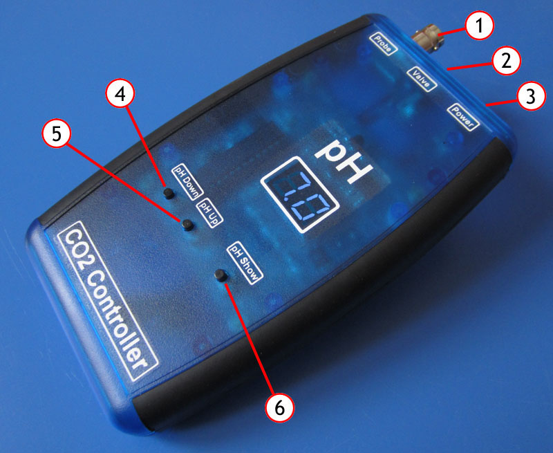 In the middle of the controller you will find the LED display showing a pH-value of 7.0 When they light, they are bright blue. The display will only show values when a button (6,5,4) is being pushed. When button (4) "pH Down" " is pushed, the display will show the "user required" pH-value and the regulator will adjust the environment in the aquarium accordingly. When button (5) "pH Up" " is pushed, the display will show the "user required" pH-value and the regulator will adjust the environment in the aquarium accordingly. When button (6) "pH Show" is pushed, the display will show the "actual" pH-value in the aquarium. The Carbon regulator will always regulate to achieve "actual" pH equal to the "user required" pH value. For example: : Let's say that the "actual" pH (real pH in the aquarium) is 7.2 You wish it to become 6.6, so you push "pH Down" until display show 6.6 The Carbon regulator system will now start to inject CO2 in a controlled way until the pH is equal to 6.6 and keep it there. This is the basic function of the three buttons. Acoustic alarm The Acoustic alarm can be activated as a supplementary function. This is expedient when the Carbon regulator controller is installed in the base cabinet of the aquarium, for example: If the "actual" pH-value (real pH in the aquarium) and the "user required" pH-value differ more than +/-0.2 units, an acoustic alarm will start to beep from a speaker inside the unit. This is a warning that something is wrong with the regulating system. Most often it will have to do with empty CO2 tank or a hose that has jammed or popped off. During large water change and during start up of the system, you will most probably have a difference in actual and user required pH-value and therefore you will get an acoustic warning. As soon as the system stabilizes, the warning will turn off. If you do not like acoustic warning, you can simply turn the function OFF. How to turn ON/OFF the Acoustic alarm Press down on button (6) "pH Show" for several seconds. The display will first display the actual pH value and after 10 seconds the display will show L7, L6, L5, L4, L3, L2, L1, "blank display" A0, A1. Performance test Below you will find logged test measurements of an aquarium equipped with the Carbon regulator. The user required pH-value for this test is set to 6.5. From the beginning the pH-value is almost at 8. The Carbon regulator adjusts the CO2 gas and the pH-value starts to fall. After 23 hours (red time line) the pH-value has fallen to 6.5 (our user required value) and stays there. As you can see from the graph the pH value in the aquarium is now stable. The pH-value does not differ 0.01 units from the "user required" value, perfect! The Carbon regulator will keep the pH levels in the aquarium at 6.5 as long as we have CO2 gas to add to the system. The time taken to obtain stable pH-values is dependent on size of aquarium and gas pressure supplied. We do not want to drop pH levels to fast as it can chock the inhabitants of the aquarium. The carbon regulator can communicate all measurements to any computer. All measurement can be sent to a computer wireless (bluetooth).  Calibration of the system 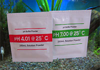 All pH level measuring systems need a calibration procedure.
Most CO2 systems today, need complex calibration including trimmer potentiometers and screwdrivers. Our Carbon Regulator is very simple to calibrate, no trimmers and no screwdrivers. The common way to calibrate a pH probe is by using two reference solutions with different pH-values. You put the pH probe into one solution e.g. pH 4.0 and trim for 4.0 reading, then put the probe into the other solution e.g. pH 7.0 and trim for 7.0 reading. pH Buffer Powder last 15-20 calibrations and can be found in our Shop Our Carbon Regulator makes the procedure very simple: Put the pH probe into one solution e.g 4.0 and push the button (6) "pH Show". Press down on button (6) "pH Show" and at the same time press down on button (4) "pH Down". The display will now show "PL" and you can release the buttons. The Carbon Regulator has now measured the reference of the 4.0 solution and stored the result into its memory. Put the pH probe into the other solution e.g 7.0 and press down on button (6) "pH show". Keep button (6) "pH Show" pressed down and at the same time press down on button (5) "pH Up". The display will now show "PH" and you can release the buttons. The Carbon Regulator has now measured the reference of the 7.0 solution and stored the result into its memory. (All calibration is saved in memory even if power is turned off.) Calibration is now completed. Prior to calibration it is advisable to wash the pH probe with deionised water before you put it into the calibration solutions. You do not want to contaminate the solutions with each other and get false calibration. Download Calibration guide Important: All Carbon Regulators in our shop are pre-calibrated, and need no trimming, you can just plug and play. Factory Reset All Carbon Regulator system comes with pre stored calibration settings. It is very simple to reload the factory settings: Press down on button (6) "pH Show" for 30 seconds. When pressing down on button (6) "pH Show", the display will first display the actual pH value and after 10 seconds the display will show L7, L6, L5, L4, L3, L2, L1, "blank display" A0, A1 and finally after 30 seconds the display show "FF". When Display show "FF" you can release the button. All factory values are back into the system and you have a factory calibrated working Carbon Regulator. The reason you have to wait 30 seconds is because we do not want to load factory setting by mistake. It should only be loaded when required. Set valve time L7, L6, L5, L4, L3, L2, L1 The valve time is is a fine tuning option you can perform for your aquarium. The default value L4=5 seconds works well with all aquariums. When you keep pressing down on button (6) "pH Show" for 10 seconds the display will show L7, L6, L5, L4, L3, L2, L1. L1 to L7 represent the time which the solenoid valve is set to open each time it is activated. (How often the valve is activated is controlled automatically by the controller) In simple terms, L1 to L7 represent the water volume.
It is most often gentler to inject gas for shorter times and more frequently than to inject longer time and less frequently. A smaller tank 5 gallon (20 litre) works better with shorter time L1 or L2, while 53 gallon (200 litre) could use L3 to L5. L1 to L7 valve time is NOT critical, L4 will work well with all tanks, but certain environment may require specific settings. The valve will always stay cold and never develop any heat due to the short valve time. How to set L7 to L1? It is very simple, release the button at the required (L7 to L1) time and the setting is established. e.g you press down on button (6) "pH Show" for 10 seconds and the display shows. L7, L6, L5, L4 and you release the button. You have now set the max valve time to 5 seconds. |
|