Super improved AM-Receiver for Aircraft.
This is the third receiver I will explain to you.
This receiver is built on a minimum number of components
and with superior performance of all my previous receivers.
This receiver will be better than most scanner on the market today!
The receiver is VERY stable, low noise-level and easy to build and tune.
All contribution to this page are most welcome!
Background
I will not give you much more background about aircraft communication than in my previous projects 118.html and
118synt.html about Aircraft receivers.
Aircraft communication is still AM modulated and the frequency is about 110-125 MHz.
What differ this construction from my two previous is that I have implemented many blocks into one
circuit and therefore I will have superior performance with less components.
The receiver is working with a Frequency Synthesizer which gives a very stable reception and it
is easy to change frequency as well.
So, lets jump directly to the blockdiagram, shall we.
Block diagram
The RF signal is first amplified before it enters mixer 1. To mixer1 is also a VCO (Voltage Controlled Oscillator). The tuning voltage to the oscillator is controlled by the PLL synthesizer. There is also a feedback from the output of the VCO to the PLL synthesizer. The synthesizer will control the VCO-voltage until the frequency is locked to the desired frequency you have programmed into the PIC circuit.
The product of the mixer 1 is filtered into a standard 10.7MHz ceramic filter and then enter
mixer 2. At mixer 2 the RF will be mixed with a constant frequency from a crystal (10.245MHz).
The product will enter a new ceramic filter and finally into a AM demodulator which brings out
the audio.
Do you think its to many blocks!
Don't worry, both mixers and VCO is in the same circuit, great!
Lets make a frequency calculation:
Let's say I want to receive a broadcast at 118 MHz.
The product from mixer 1 should be 10.7MHz so the VCO should be
118
+ 10.7 = 128.95 MHz
If I have an RF at 118MHz and mix it with 128.95MHz
I will get 10.7MHz out from mixer 1, okay!
Since the ceramic filter is made for 10.7MHz (Lucky us) the signal will pass into mixer 2.
Here the 10.7MHz RF signal will mix with 10.245MHz
and the product will be 10.7 - 10.245 = 455KHz.
Again we have a filter at 455kHz (double luck) and the RF will enter the AM-demodulator.
Schematic Preamplifier:
To the left you will find the preamplifier. It is based on a dualgate fet (You can use almost any dualgate fet).
At Gate 1 we have the antenna input.
L1 and C1 will tune the antenna for best performance. To find super perfect antenna match you can solder the antenna to a tap-point of L1. I can not tell you where to put the tap, you have to experiment yourself.
Gate 2 is biased to give high gain. At drain you will find another tuned circuit L2 and C2.
This circuit should also be tuned for best performance. I have chosen L2 to be a transformer
slugtuned Inductor.
I have an inductor with AL value of 7. With 5 turns primary I will get 5*5*7=175nH.
This inductor transform the RF to the secondary side 3 turns which is connected to mixer 1.
Mixer 1 and Mixer 2:
In the MC13136 you will find an oscillator at pin 1 and 2. This oscillator is connected to mixer 1.
To pin 1 and 2 is a tuned circuit connected C3 and L3.
How to make this oscillator voltage controlled?
Between pin 24 and 23 is a varicap diod. The capacitans of this diod is dependent of the voltage over it.
Look at the schematic and you will find a small 10pF capacitor connecting the varicap and the C3.
So, by applying a voltage to pin 24 you will now be able to change the frequency a few MHz.
Forget about that now and look at mixer 2. You see how the RF signal goes from mixer 1 through the ceramic filter into mixer 2. At pin 5 and 6 you will find a fixed oscillator with a crystall.
This oscillator is always 10.245MHz (hopefully). The 455KHz IF is now passing a ceramic filter and to the AM demodulator. At Pin 15 you will have a voltage depending on the strength of the input RF signal (RSSI).
This voltage can control a squelsh unit.
PLL synthesizer:
Many people get scared when it comes to PLL stuff. Don't worry I will explain to you.
Earlier I told you that the oscillator was at pin 1 and 2. Well, at pin 2 I have added a 10k
resistor to ground because I want to amplify the oscillation current. A fraction of the
oscillation energy slips away through a 10pF capacitor down to a FET buffer. This buffer
is needed because I don't want glitches from the PLL go back into the VCO and I don't
want to load the VCO to much either. At pin5 of the PLL I will have the VCO frequency
amplified. Pin 3 of the PLL is the Phase detector output. The PLL will regulate
the current at this pin and with some capacitor and resistor I will have a voltage
which is feed back to the varicap at pin 24 of the MC13136 through a 100k resistor.
If you want you can probe (schematic Vtune) this voltage with a voltmeter and you
will see how it keeps the frequency locked.
Example:
I connect Vtune to ground and measure the VCO to 127MHz.
I then connect Vtune to +5V and measure the VCO to 132MHz.
I now know that 5 Volt tuning will change the frequency with 5MHz.
If I now program the syntesizer to 129.5MHz I will probably have 2.5V at Vtune.
AM demodulator:
There are many AM circuit out there on the market, but I found a great circuit in a
cheap radio I bought for 5$. Inside I
found CXA1619. This circuit has a AM
demodulator and a audio amplifier of 250mW.
The demodulator output is at pin 23 and the amplifier input is at pin 24.
So by connection them together I can amplify the audio into a speaker. If you want you can connect a squelsh control here.
The final part is the PIC microcontroller:
The purpose of the PIC is to set the registers inside the PLL synthesizer.
One important thing with the PIC and synthesizer is that the PIC is working with +5V and the PLL synthesizer is working with +3V. Therfore I have added resistors at the output pin of the PIC to lower the voltage to +3V.
How should you program the frequency of the PLL?
There is two registers inside the PLL to set the frequency.
The registers name is B and A.
The frequency of the VCO is calculated in this way:
VCO frequency = 25000 * (64 * B + A)
Example: I want to receiver at 118MHz. Remember the IF of my receiver is 10.7MHz, so
then the VCO should be 118 + 10.7 = 128.8MHz.
128.7e6 = 25000 * (64 * B + A)
I get that B = 80 and A = 28 B = 80 dec = 50h A = 28 dec = 1ch
EEPROM data-adress 00h - 3fh in the PIC can be set when the circuit is programmed with the
Program code.
I have chosen adress 00h to hold the content of A register and
adress 01h the content of B register.
When you download the program code to the PIC you should set EEPROM data-adress 00 and 01 like this:
EEPROM data address 00h should be 1ch
EEPROM data address 01h should be 50h
Now the PLL will keep the VCO to 128.8MHz.
Not difficult ha!
If you are familiar with PIC programming you can make software yourself so the receiver will scan
several frequencies and you might also implement display etc.
In reality the register A and B is one 22bit long register in the PLL synthesizer, but
I have separated them so it will be easier for you to load them into the PIC. If you
look into the datasheet of LMX2337.pdf you will find the 22 bit register and you can read
all about the details.
Building and testing
I advice you to build this receiver in several blocks. First you should get the VCO working. Wait to
solder the PLL LMX2337 circuit. If you have a frequency counter you can check the frequency at the drain of the FET
transistor. You can now also connect Vtune to ground
resp +5V and make sure the VCO frequency changes, and is in the range you wish.
The AM demodulator is not much to do about. If you can find this exact circuit, you can always buy
a cheap radio and use the am demodulator. Before you solder the PLL you should also make sure that all
voltage are correct. The PLL should run on +3V and +5V. Connect the PLL and now you can monitor the Vtune
voltage with a DC meter.
By changing the frequency you should also see that this voltage change.
Finally you can add the preamplifier.
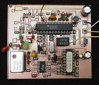
My hardware
This is a photo of my receiver. In this photo, I have not yet implemented the preamplifier.
Aircarft receiver program (the hex file is zipped!).
Final word
This project is a kick start for your Aircraft scanner project.
Here I have given you the basic structure how to build an aircraft receiver controlled by a PLL circuit.
When you get the receiver working you can add display, scanning function, automatic squelch control,
and much more.
You can always mail me if there is anything unclear.
I wish you good luck with your projects and thanks for visit my page.
 Super improved AM-Receiver for Aircraft.