 Blockdiagram of a TUNER
Blockdiagram
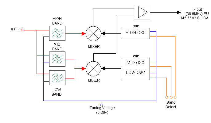
This is a very simple blockdiagram over a tuner.
The RF signal is entering bandfilter before it enters the mixers. There are two mixers, one for the UHF and one for the VHF.
Two oscillators are connected to the two mixers. One for the UHF and one for the VHF. The VHF oscillator is divided into two band BL and BH.
The band can be selected with the input called BL, BU, BH. The frequency of the oscillators is controlled by a voltage called
VT (tuning voltage).The output from the mixers is the IF signal.
The frequency of the IF differs from European standars to American standard,
the Eurorpean tuners has an IF of 38.9MHz and the American is 45.75 MHz.
The input called ACG (Automatic Gain Control) controlls the gain of the signal. This signal effect many part in the tuner so
I haven't drawn it in the block diagram. The input AFC (Automatic Frequence Control) adjust the frequency of the oscillator a bit. This input is a
feedback from the VIDEO-IF circuit to obtain easy tuning. I have excluded this also.
© Max Last modified on 6th Feb 2001.