Crystal controlled transmitter
This is a 1-transistor transmitter. The transmitter use a crystal 46.515MHz to hold a steady frequency.
This unit can not send audio information, it is made to send data. The output power is about 10mW into 50 ohm.
All contribution to this page are most welcome!
Background
The reason I am building this unit is to learn how to make transmitters. I will continue to build more and more
powerfull transmitters. This first transmitter will be used to send some kind of data (zeros and ones). I will use this
transmitter with a PIC16F84 processor and send some basic data over a distance. The interesting part will be how
long distance I can transmitt, and the overal performance of this unit.
This transmitter is basically a crystal-oscillator. I found the 45.515MHz crystall in an old cordless-telephone. I guess you can
find somewhere to buy crystals. The important thing is that the transmitter crystal is 455kHz lower than the receiver crystal,
because the IF of the receiver should be 455kHz. The ceramic filter in the receiver is matched for 455kHz IF-signal.
The receiver for this project can be found here!
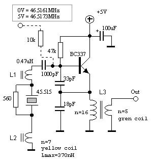
Scheamtic
The crystal I used is a 3:th overtone crystal. L1 is a standard coil of 0.47uH. This coil is not so critical in value. If you are
going to use other frequency you might have to change the value of this coil try some different values.
L2 is a slug tuned coil (a tunable coil).
You can use almost any coil core to make this coil. You might have to play a bit with the numbers of wire-turns.
I have added this coil to be able
to change the oscillating frequency a bit. I noticed when I increase the power (by adding a 10k resistor to plus) the frequency will
change for a few kiloherts. The reason of this is the internal stray-capacitance in the transistor is voltage dependent and change
the overal resonans frequency.
Since I only want two different frequencies, one representing zero and one to represent ones. I can simply use the input to
the 10k resistor to modulate the transmitting frequency.
L3 is a impedance transformer. It transform a low impedance (like 50 antenna) to bit higher impedans to the transistors emitter.
This coil is not nessesary, most often one see a resistor here instead (1kohm). I have added this coil to increase the power and
to get a better match to the antenna. This coil is not critical either, the important thing is that rhe coil can handle the actual frequency.
Output power
Impedance
Power (mW)
>1Meg.
690mV
51 ohm
5.5mW
10 ohm
10.2mW
As you can see in table above, when there is no load at the output there is no power, only a voltage.
When the 10k resistor to the base of the transistor is connected to plus the output power increase and
the frequency change. Table below shows the output power in this case.
Output power
Impedance
Power (mW)
>1Meg.
940mV
51 ohm
10.4mW
Performance in open field
The crystal I used is a 3:th overtone crystal. L1 is a standard coil of 0.47uH. This coil is not so critical in value. If you are
going to use other frequency you might have to change the value of this coil try some different values.
 Crystal controlled transmitter