Click on the pic to see a largeer photo with info. Automatic Frequency Control (AFC)
What is AFC?
This project is to give you a glimt about the advantage of using AFC.
The tuning part in a receiver has driven many homebrewers insane!
Use AFC and you can let your grandmom do the fine tuning with no problem.
Just a few extra componets will change your receiver performance totally!
All contribution to this page are most welcome!

Background
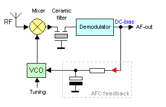
In simple words you can say that the AFC will lock the receiver to any valid RF signal. To the right you can see a basic block diagram of an receiver. The RF signal enters a mixer (yellow) and mixes with the VCO (green). The VCO can be a coil and a tuneable capacitor. The product from the mixer is filtered and enter the demodulator(blue) to bring out the sound from the FM signal.
Out from the demodulator you will have the AF signal which is a DC signal with an AC component. The AC component is the audio and the DC component is a bias. The bias contains lot of information which will be used by the AFC unit. Let's say that the modulator works at 455kHz.

If you have tuned the receiver (VCO) perfect to the RF component you will have a 455kHz out of the mixer. The demodulator will then have a constant bias of a few volt and an AC component which will be the audio. The VCO is a very sensitive unit and can change frequency just by hand-effects.

If you now, change the VCO just a few kilo Hertz, the product will be 455kHz +/ - the tuning error. The demodulator will now have a different bias voltage depending on the frequency error of the VCO. The AC component will still be there, but a bit distored. As you can see, the DC bias from the demodulator is filtered by a resistor and a capacitor. The AFC feedback will after the filtering regulate the VCO to correct it so the frequency will slide back to the 455kHz and you will have pefrect reception again.
Next picture will explain better.

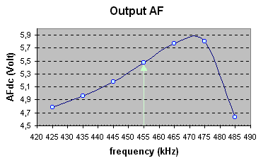
Okey, look at the diagram at right.
This is a measurement I did on a FM receiver (MC3372). I have plooted the output DC-bias as function of the IF (Intermediate Frequency) frequency. At 455kHz you can see that I have 5.5V DC bias. When I change the IF frequency the bias will also change in both ways. This bias will work at 455kHz +/- 20kHz (linear are). If you go outside this range the filter is self will reject the frequency. The charper filter you use the smaller AFC range you got.
Now imagin I want to receive at 100MHz. I tune my receiver to (100MHz - 455kHz = 99.545MHz) and I receive the radio station. With perfect tuning the DC bias will be 5.5V DC and I will have an AC audio signal also. If I now change the VCO by decresing the frequency with 20kHz the IF will also decrease with 20kHz and my DC bias will dropp to 5.0V according to my measurements. The reception will be bad. The output AFC filter is connected to the VCO and inside the VCO is a varicap. The varicap will now change its capacitance because of the voltage dropp. When the varicap change capacitance the VCO will increase in frequency until the IF frequency is back to 455kHz.

The AFC is simply a feedback regulating system to keep the VCO locked to a valid RF signal.
The lock range in this example is 40kHz. It means that if you are +/- 20kHz close to a RF signal the AFC will lock the reception to that RF signal which will simplify tuning soo much.

How does it feel to tune with AFC
Now you wonder how much difference there is in in tuning with or without AFC?
Without AFC you have to be very steady on your hand, and if you touch any component the frequency will change.
This i specially enoying when you are trying to find narrow band signals.
When the AFC is connected I just let the tunable capacitor slide and my receiver locked to all kinds of signals.
I could even locked the receiver to a police frequency witch is narrow band FM signal (5kHz).

Hardware
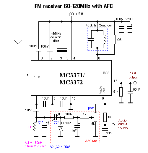
Below you can see the schematic of a simple FM receiver with AFC.


The schematic show you a basic receiver circuit. L1 and C1 is the tuning part (VCO). L1 is fixed so the tuning is done with C2 which is a tunable capacitor. I have choosen L1 so you can use it in a wide frequency spectrum. The RSSI output indicates the strength of the incoming RF signal. Audio output is a low level output which need to be amplified in an audioamplifier.
The few components in the dashed red box is the AFC unit.
The DC bias from the audio output is smothed out by the filter (pot1 + 1k + 1uF). The bias will then regulate the capacitans in the varicap diod BB132 Since the varicap and the tunable capacitor C2 are parallel to C1 the tuning frequency will change according to the feedback of the bias voltage.
You have now a regulating system to keep the VCO locked to the RF signal.
With the capacitor C2 and the pot1 you can set the magnitude of the regulating feedback. A high value of C2 will make large frequency change of the VCO. You will have to experiment to find good locking. It is not so critical. About 12pF of C2 gave me good locking of RF signals.

More info about the AFC regulation
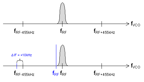
Lets have a look at the frequencies for this receiver.
The top figure show you the spectrum. At fRF you have the radio signal you want to receive. Since the IF (Intermediate Frequency) of the receiver is 455kHz, the fVCO can be ± 455kHz from the fRF. In both case you will receive the signal.
Let's focus on the lower side and look at the bottom figure. Imagin that something has made the IF increase with +10kHz.
The IF is defined as the frequency from the fRF and with a +10kHz increase the deviation goes to the left. The short blue line show you the deviation. The long blue line show you the new receiving frequency and as you can see we misses our RF signal. From my measurement earlier I found that +10kHz IF will increse the Vbias. If the Vbias increase the capacitance in the varicap will decrease and that decrease will make the fVCO increase in frequency. If the oscillator (fVCO) increase the blue line will be pulled to the right and back to be locked to the original black fRF. This regulation will continue as long as the IF stay with in the ± 20kHz (locking range).


Download some datasheets
mc3372.pdf Datasheets for mc3371/mc3372
BB132_3.pdf Datasheets for BB132 varicap

Final word
This project explain how a AFC works. Build a little receiver and test it with and without the AFC.
You will have lot of fun.

You can always mail me if there is anything unclear.

I wish you good luck with your projects and thanks for visit my page.


Back to main Page  |  Contact Me  |  Cheap components

Copyright © Last modified on 4 jan 2003.