Front end design of antenna
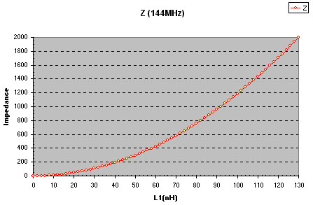
This side will explain how to calculate the tap point on a
coil to match the antenna input for receivers.

All contribution to this page are most welcome!

Background
After study many construction I found that the antenna was conected to a tap point at the input coil (L).
Why should an antenna be connected to a tap point at L?

I have asked many persons, but always received a blurry answer.
The answers changed as if the subject was how long time the chicked should be in the owen.

I turned my research back home and worked with some old fashion Jw-method during a weekend, and voala, I finally understod it!

Theory
If an antenna is connected to the top of the coil L, the antenna will load the coil so the Q will be low at this point and the selectivity will be poor.

To achive good antenna match and antenna performance, the impedance where the antenna is conneted to the coil (L) should be the same as the antenna impedance. In such case the antenna will not degrade the Q-value and the selectivity will be much better.

To prove this argument I have been playing with some Jw-method and I will explain how you can calculate where the tap point should be. I will also show some diagram of the calculation and some of the simulation.


In the picture above you will find a LCR input stage (fig.1). The antenna is connected to the coil L at a tap-point. Coil L can be split into two coils L1 and L2 (fig.2). I transform the two coils to reactances XL1 and XL2 and the same with the capacitor to XC (fig.3). I have drawn the reactances as resistors. The nice thing to calculate with reactances, is that after transforming L to XL and C to XC, you can calculate the network as it would be a simple resistor-network (parallel and serie couppled) (fig.4).

If you are not familiar with the method you can just look ad the final equation (the one in the blue frame). I will explain more later how to use this equation.

Z is the impedance wich will be connected to the antenna. To find the impedance Z I have to consider the whole network.
Below you can follow how I calculated the total impedance Z.


HOW TO USE ALL THIS Jw-blurr?

Look at fig. 1 again, where you got the L and C and the resistor R. Don't mind about the tap point yet. Consider L as one coil. The first thing you should do is to define L and calculate the value of C so the resonans will be at desired frequency.

Example: you want to receive at 144 MHz. You starts to make a coil L to be 130nH. Since f=1/(2*pi*rot(LC)) you calculate C to be 9.39pF.
Since we made L to be 130nH, and we split L into L1 and L2 the total inductance of L1 and L2 should also be 130nH. If not , the resonans frequency will change.
R is the impedance of the pre-amplifier. In this example R = 2000 ohm.

If we have an antenna of 50 ohm we know that Z also should be 50 ohm. How can we find the relationship betwen L1 and L2?
We know that the sum of L1 and L2 must be 130nH.
Well, the easiest way is to put different values into L1 and L2 and use the formula in the blue frame to calculate the impedance Z !
We know the frequency is 144MHz and therfore w = 2* pi *144MHz.

The table below shows the different Z for different relationships between L1 and L2. I started with L1 to be 0nH and L2 to be 130nH. I increased L1 with 10nH and decreased L2 with 10nH for each step. The total sum of L1 + L2 will always be 130nH.

w L1 (nH) L2 (nH) C (pF) R Z
904778684 0 130 9.4 2000 0
904778684 10 120 9.4 2000 11.8
904778684 20 110 9.4 2000 47.3
904778684 30 100 9.4 2000 106.5
904778684 40 90 9.4 2000 189.3
904778684 50 80 9.4 2000 295.8
904778684 60 70 9.4 2000 426.0
904778684 70 60 9.4 2000 579.9
904778684 80 50 9.4 2000 757.4
904778684 90 40 9.4 2000 958.6
904778684 100 30 9.4 2000 1183.4
904778684 110 20 9.4 2000 1431.9
904778684 120 10 9.4 2000 1704.1
904778684 130 0 9.4 2000 2000


More interesting details

As you can se in the table, the tap point should be where L1 is 20nH and L2 is 110nH. At this point Z will be 47.3 ohm and close matched to the antenna.

Another interesting value is the last value. In this case L1 is 130nH and L2 is 0 nH wich means that the tap point is at the top of the coil. In a parallel circuit L and C takes out eachother and you have a pure resistive resistance. In this case we have a resistor of 2000 ohm and as you can se in the table Z is 2000 ohm.


The Z impedance curve.

The diagram below show the Impedance Z as function of L1.


How about the selectivity.

I have made two ORCAD PSPICE-simulation where the tap point is at top of the coil (RED curve) and on where the tap point is at 20nH from the cold end (GREEN curve).The input is 1uV and I have measured the voltage into the amplifier (the voltage over resistor R).
The diagram speaks for it themselfs.


Finally

I hope I have brought some light over the subject front end design of antenna.If you have experience or nice ideas, don't hesitate to share them with the rest of us. I have not yet made any hardware experiment about this subject,maybe you have?


Back to main Page  |  Contact Me  |  Cheap components

Copyright © Last modified on 15th May 2001.