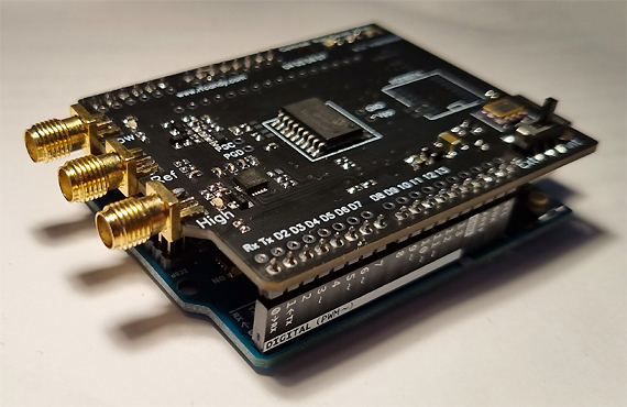
 Arduino Frequency Counter Shield
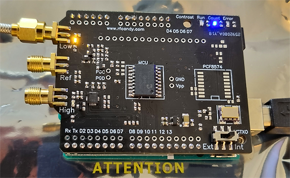
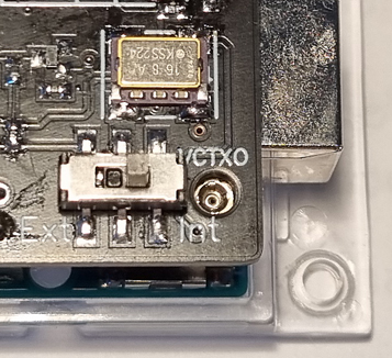 Gate time/Reference oscillator

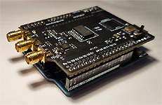
 Hardware and schematic
// Filename : CounterBasic.ino

#include <SPI.h>


// ==============================================================================================================
//                                              Define Pins
// ==============================================================================================================

// Pins below are used by the Counter PCB and can not be changed
#define Ready 3                                                       // Define Ready Pin
#define Trigger 2                                                     // Define Trig Pin
#define RFInput 4                                                     // Define RF input Pin

// ==============================================================================================================
//                                           Define Variables
// ==============================================================================================================

long Incomming_Data=0;                                                // Counter Value

// ==============================================================================================================
//                                              SETUP
// ==============================================================================================================

void setup(){
    Serial.begin(9600);                                               // Init serial

    pinMode(Trigger, OUTPUT);                                         // Set Pin as Output
    digitalWrite(Trigger,LOW);                                        // Set Pin Low
    pinMode(RFInput, OUTPUT);                                         // Set Pin as Output
    digitalWrite(RFInput,LOW);                                        // Set Pin Low
    pinMode(Ready, INPUT);                                            // Set pin as Input
    delay(500);
}
// ==============================================================================================================
//                                              Loop
// ==============================================================================================================
void loop() {

    Incomming_Data=GetCounterValue(0);                                // Get Counter Value Low input
    //Incomming_Data=GetCounterValue(1);                              // Get Counter Value High input

    Serial.println(Incomming_Data,DEC);                               // Print out counter value
    delay(10);
    }
|
// LCD_Display.ino
#include <SPI.h>
#include <Wire.h>
#include <LiquidCrystal_I2C.h>


#define PCF8574_I2C_Address 0x27                                      // Define the I2C address

// ==============================================================================================================
//                                        Define LCD display 2x16 Char
// ==============================================================================================================

LiquidCrystal_I2C lcd(0x27, 16, 2);                                   // LCD address to 0x27


// ==============================================================================================================
//                                              SETUP
// ==============================================================================================================

void setup(){
    Wire.begin();                                                     // Init I2c
// LCD Initiering
    lcd.backlight();
    lcd.init();                                                       // initialize the lcd
}
// ==============================================================================================================
//                                              Loop
// ==============================================================================================================
void loop() {

    lcd.clear();                                                      // Clear display
    lcd.setCursor(0, 0);                                              // Position
    lcd.print("Hello World");                                         // Print
    delay(1000);
    }
|
Download Arduino Software examples |
|
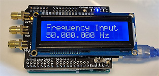
Example #1:
This example is the most basic one and the counter will measure frequency and send the result over serial line. No display is used. File CounterBasic.zip (2k) Example #2: This example will only show the text "Hello World" on the display. File LCD_Display.zip (2k) Example #3: This example trig the shield to start measure frequency on LOW input. The result will be presented on the display. File counterDisplay.zip (2k) Example #4: This example trig the shield to start measure frequency on LOW input. During the measurement, the Arduino will do something else, in this example make the LED blink on Pin 13. This example demonstrate how the counter shield can work on its own and Arduino is doing something else at the same time. File CounterNoDelay.zip (2k) Example #5: This software use an external switch to select RF input Low or High. The switch should be connected between GND and to D5 of the Arduino When switch is off, D5 will be pulled high by internal resistorand RF High input will be selected When switch is on, D5 will go low and RF Low will be selected. Display will handle a printing and add dot to the measurement eg 2.500.000.000 Hz File LCDdot.zip (2k) LiquidCrystal I2C Library: Library how to install |
|
 Order a KIT
which will include all parts |
|||
|
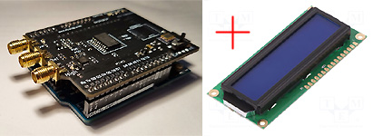
This shield can be ordered in 3 different Configurations.
The reason is that some people wants the shield only, other wants to connect the display themselves using cables. Some people want the display assembled on the shield.
|
|||
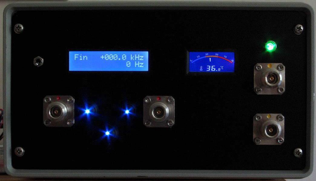
Bob from USA 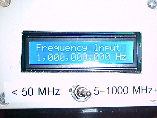 Bob sent me this picture showing his cool box. A switch is used to select frequency input. Project Link file: noLeadingZeroComma.zip file: noLeadingZeroDot.zip |
Russ from USA 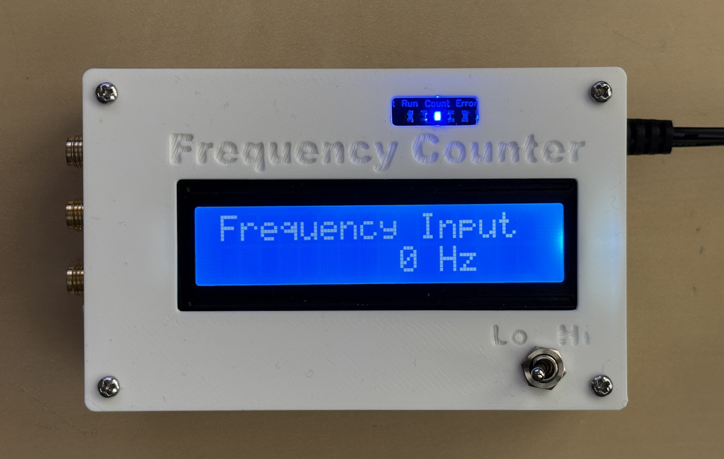 Russ sent me pictures showing his 3D printed enclosure. He shares his 3D files and more picture below, great work. Enclosure_2.jpg, Enclosure_3.jpg,Enclosure_4.jpg 3D files: Model files here at Printables |
Share your work here!  Share your work or software here so other can be inspired |