Explore inside of a Radio
This page investigates the inside of a cheap beach radio.
I will show you different compontents and explain what they do. There are lot of stuff you can re-use from such radio.
All contribution to this page are most welcome

Background
The are lots of cheap radios on the market. Specially in summertime. Well, what do you get from such a radio. You get some coils, ceramic filters, radio-IC, speaker and lots of other compontents. If one would buy these parts seperatly you would have to pay quit lot. When I get a radio I usually try to find the datasheet for that IC in the internet. The radio I have here use a circuit called CXA1191. I will identify some compontens and you will be able to find them at the schematic. I will specially explain the 455kHz AM IF filter, (Yellow can) wich can be used as a quad coil for your projects.

Let's open the cover and have a look inside.


To the left you can find a speaker and below the speaker you will find the ferrite rod used as a AM antenna. The radio IC is in the middle of the board. Above the IC you will find a ceramic filter (10.7MHz) for the FM part. This filter is blue. At the top you will find the yellow AM IF filter. This filter is a 455kHz tuned filter. The slug is in yellow color. You can use this filter as a quadcoil because it is a LC unit tuned to 455kHz. There is two more cans. One is red, this is the AM oscillator (0-2MHz). The can with pink color is a quadcoil for the FM demodulation. This can is a LC unit tuned to 10.7MHz. At the right side you will find 2 tuning things. The one at the top is the volum control and the one at the bottom is a variable capacitor. Actually it is four tunable capacitor in one house. Most often there are two in the range 5-30pF and two with the range 10-130pF. At the right side of the IC, a few cm above the red can you can find a aircoil. This coil is connected to the antenna and acts as an antenna filter. The rest is for the audio part. One thing you should notic is that this radio doesn't have a ceramic filter for 455kHz . In the schematic you might find this filter in serie with the yellow can, but this radio is of lower quality and the have left it out.

Closer look at the filters.
Top layer of the 455kHz IF transformer and the ceramic 10.7MHz filter

Bottom side


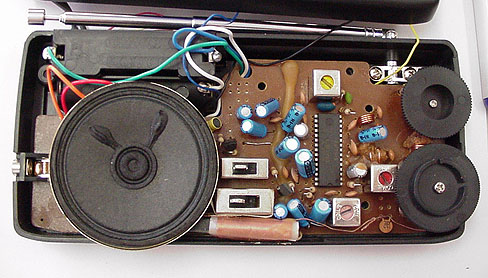
Here you can compare the left pic with the bottom layer. Don't forget, the bottom layer is mirrored compare to the top layer!


The schematic of the CXA1191
If you click on the pic you will see the original full scale schematic of the CXA1191.
The photo above show you the ceramic 10.7MHz filter and the (AM filter) 455kHz can with yellow slug.
If we take a closer look at the schematic you will be able to identify the components. Everything inside the red box is actually inside the can with yellow slug.
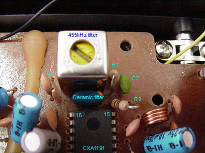
The product from the mixer comes out at pin15 and the FM signal passes through the 10.7MHz ceramic filter and the 455kHz AM signal filters in the can.The primary winding in the filter is actually from pin1 to pin3 and the cap is also connected to pin1 and pin3 (fig at right). There is a tap point from the primary winding to pin2. In this schematic they have drawn it to look like the winding is from pin2 to pin3 wich is not true, but this is just details because the filter will work the same, the only thing is that the impedance into the filter is different if you use pin1 or pin2. Pin3 is always used.
If you are going to use this filter as a quad coil I recommend you to use pin 1 and pin 3.
The filter has a secondary winding from pin4 and pin5. The output from the filter goes back into the IC at pin 17 and the FM goes into pin 18.

So, crack open some radios yourself and do some exploring.


Back to main Page  |  Contact Me  |  Cheap components

Copyright © Last modified on 12th Jan 2002.