RF field meter
This project will explain the function of a simple RF field meter.
The unit will be in great help to tune transmitters for best performances.
All contribution to this page are most welcome!
Background
Most transmitter has several variable capacitors which are used to match impedance for transistors
and antennas.
I know people hate trimmers and so did I. The reason is that it is difficult to trim a system
if you can't measure the performances.
To trim a transmitter you need to measure the output power.
Most transmitter are tuned with a dummy load of 50 ohm to substitute an antenna of 50 ohm.
Not everyone has a power meter, and how can you know that the antenna you connect is purely 50 ohm.
If not, the hole trimming is waste of time!
What you would like to do is to measure the radiated power out from the antenna you actually
are going to use.
If you can measure the radiated energy field you can easy tune the system for max output
field strength (max power).
So, how can we measure the radiated energy field?
Block diagram
The block diagram at right show you one easy way to measure the RF filed strength.
To the left you find a dipole antenna.
The antenna should be cut to match the receiving frequency.
The length of antenna is not a critical at all.
Length = 0.95*300/(4*freq) <= (freq = Mhz)
The RF signal is then rectified in a diode and the DC voltage is then amplified in an OP-amplifier.
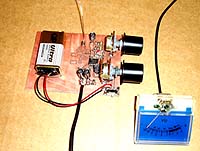
To display the voltage I use a panel meter.
The amplifier gain can be set with a potentiometer and I have also added a bias voltage
to set the zero level of panel meter.
This unit will not show you the exact power like a power meter, but it will show you the relative
power transmitted out from your transmitter and antenna. The panel meter is connected to the PCB with 5 meter long wire.
In this way I can put the field-meter 5m away from where I am and still be able to watch
the panel meter.
I will tell you how I use my filed meter.
I place the RF field meter 5 meter away from my transmitter.
I then put all variable capacitor to middle.
I switch on the transmitter and go to my RF filed meter. I then set the gain (with potentiometer)
so I get half of max reading on the panel meter. I then switch off the transmitter and set
the offset (with other potentiometer) so I get zero reading on the panel meter.
I repeat this tuning process unit it looks good.
Now I can start tuning the transmitter and watch the panel meter.
All I need to do is to tune for max reading on the panel meter. Then I know the RF field is at
max strength.
I also advice you too receive the signal you are transmitting to check that it
sound good.
I also check the current to the transmitter so it don't get to high.
Usually the current go down when good tuning has been done and you got max power.
Another good thing to monitor is the temperature of the transistors.
Don't let them go to hot.
I find my RF field meter to be a very simple and powerful too.
This RF filed meter works from 30mW to several watt.
Hardware and schematic
Please look at the schematic to follow my function description.
At the bottom left corner you will see a voltage divider. This divider is to produce a
virtual ground of 4.5VDC.
Above you will find the dipole antenna.
The dipole antenna will pick up some radiated energy and the diode will rectify the RF signal
to a DC voltage at VRF. This voltage is still quit low
and needs to be amplified before it can control the panel meter.
The signal then enter the OP which amplifies the voltage to suitable level set by the "Gain"
potentiometers".
The second OP acts as a voltage follower and set the offset (zero) for the panel meter.
The panel meter is connected to the board via two wires (5meter long).
To prevent any RF signal to be induced in this long wire I have added 2 ferrite block which
will act as high impedance units.
You can use any ferrite block or large inductor (10uH).
Final word
This little unit has helped me so much to tuner my transmitter.
Easy to build and to use.
You can always mail me if there is anything unclear.
I wish you good luck with your projects and thanks for visit my page.
 RF field meter
 The block diagram at right show you one easy way to measure the RF filed strength.
To the left you find a dipole antenna.
The block diagram at right show you one easy way to measure the RF filed strength.
To the left you find a dipole antenna.