Frequency Counter
I will here by explain my easy construction of a frequency counter.
This counter is supposed to be working with a computer or a micro-computer like the PIC16F84.
All contribution to this page are most welcome!

Background
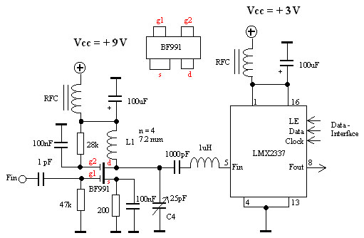
The reason why I built this frequency counter is becasue I need a (easy to build) HF-counter to my tuner project. This counter has no display showing the frequency. The frequency information is supposed to be fethed by a computer or a micro-computer and then it can be displayed on the screen or a LCD-screen module.

I have been using CMOS chip to my counter wich makes it kind of slow. The max frequency is about 20MHz. This is not much for a counter, but I will add a prescaler to it wich will make the max frequency 1.1GHz.

This frequency counter will not bet a precision instrument, but the resolution will still be 250Hz from DC upp to 1.1GHz. This counter will be easy to build and to control. Personally I like radioequipment with nice fronts and what better can you add to your radio projects if not a green LCD-display module, showing the frequency.


Block diagram
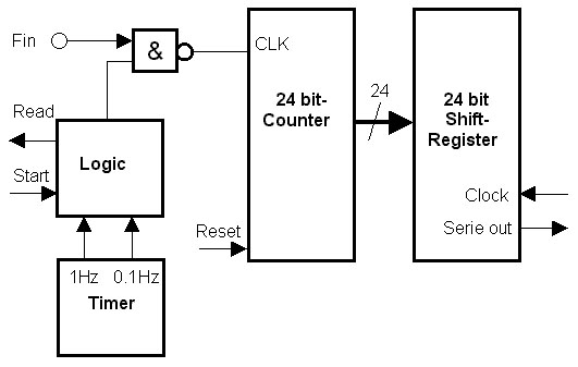
The counter is 24 bit and the 24 output are connected to shiftregisters. There is a timer wich produce 2 frequency 2 Hz and 0.2Hz. This two frequency is the measuring time. (The time under wich a measurement should take plase.) In the logic is a divider so the actual measure time will be 1 sec or in the other case 10sec.
The "start" signal activates the logic wich let the Fin be connected to the counter. after 1 sec the logic disconnect the Fin from the counter and the "Ready" signal is activated by the logic. If you want higher resolution you can let the 0.2 Hz control the logic. In this case the logic will let the Fin be connected to the counter for 10sec. If you want other measure times you can easy change it.
Mostly often i use 0.5 s and I use a prescaler wich divides with 250. This gives me the resolution of 500Hz and I get 2 measurement per second. I find this good enough.

When the "Ready" has ben activeted you can simply shift out the result from the counter via the shiftregister. The counter-data will be at serie out and the "Clock" will shit out each bit until all 24 bit are shifted out. The counter can be reseted by activeting the "Reset" input.

The whole construction can be made very compact and easy to build. One important thing is the timer that produce the measuring time. This timer is build around a 32768 Hz Crystall oscillator wich needs to be calibrated if you want accurate measurements.

Details about the schematic
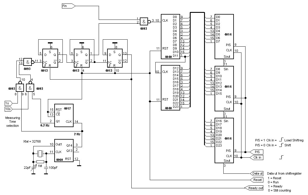
The 24 bit counter consist of two 12 bit counter 4040. Three (8-bit Parallell in - serie out) shiftregisters 4014 are connected to the counters.
When the "ready out" signal goes high the value in the counters can be loaded into the shiftregisters by holding P/S high and send a rising clock-puls. The 24-bit value can then be shifted out by lower the P/S to ground and pulsing the clock.

A crystal oscillator 4060 creates a frequency of 2 Hz. This frequency is then divided by 10 in the circuit 4017, the resulting frequency is 0.2Hz. One of these two frequencies can be send to the first 4013 by 2 control signals. The reason of this option, is to be able to increase the measuring time by a factor of ten. The first flip-flop works as a divider by 2. The output frequency will be 1 Hz or 0.1Hz. Flip-flop number 2 works also as a divider by 2, so the output frequency will be 0.5Hz 0.05Hz.
0.5 Hz means that the positive flank is 1 sec and the negativ flank is 1 sec, and 0.05Hz gives 10 sec positiv flank and 10 sec negativ flank. During the positiv flank the 4093 nand gate opens so the Fin can reach the counters. When flip-flop 3 aktivates it will lock (turn off) flip-flop 1 so there can not be any more measuring time.
The result will be that when the Reset goes low the counter will start counting during 1 sec or 10 sec. When the end of the measuring time is reached the "Ready out" goes high and no more counting can be done. The value in the counter can be fethed via the shiftergisters.

The prescaler
There are several prescalers you can use to this frequency counter. One disasvantage with lot of prescalers is that they only divide with 64 or 128.
I have grown fond in the LMX2337 Frequency Synthesizer. This circuit has a very sensitive input (10mV). One part of this circuit is a programmable divider. It can be programmed from 192 to 33538175 by a serie interface with a computer or microcomputer. Most often I divide the input frequency with 250 and set the frequency counter to measure under 0.5 sec, wich gives me the resolution of 500Hz and the uppdate will be 2 times/second.
The LMX2337 circuit is serially programmed. You can read the datasheets to find out how to set the divider.
I have added a preamplifier to the LMX2337 so there will not be any load of the measuring object.

Datasheets:
  • LMX2337


    Back to main Page  |  Contact Me  |  Cheap components

    Copyright © Last modified on 17th April 2001.