 Improved LC-meter
 So, the only way to build a fully functional LC-meter is to build one myself (as usual).
 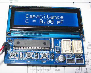 Specification of this LC-meter
 The theory behind the measurements
 Hardware and schematic
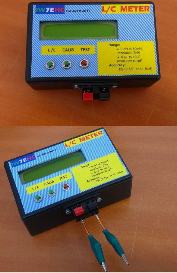
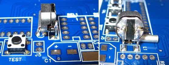
Front side  Click the picture above to enlarge! |
Back side  Click the picture above to enlarge! |

 Order a KIT
which will include all parts listed below |
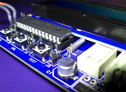
Factory produced PCB
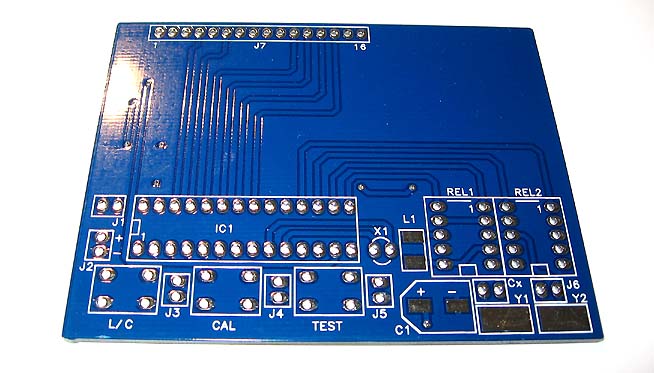 Click on the picture to see larger photo. The PCB is blue and factory made. |
|||
|
1 pcs
|
|
|||
|
1 pcs
|
|
|||
|
1 pcs
|
|
|||
|
1 pcs
|
|
|||
|
1 pcs
|
|
|||
|
2 pcs
|
|
|||
|
1 pcs
|
|
|||
|
1 pcs
|
|
|||
|
1 pcs
|
|
|||
|
2 pcs
|
|
|||
|
2 pcs
|
|
|||
|
1 pcs
|
|
|||
|
3 pcs
|
|
|||
|
2 pcs
|
|
|||
|
1 pcs
|
|
|||
|
1 pcs
|
|
|||
|
2 pcs
|
|
|||
|
4 pcs
|
|
|||
|
1 pcs
|
|
|||
|
3 pcs
|
|
|||
|
6 pcs
|
|
|||
|
1 pcs
|
|
|||
|
1 pcs
|
|
|||
|
1 pcs
|
|
|||
|
1 pcs
|
|
|||
|
Order here |
Features
|
|||
Front side 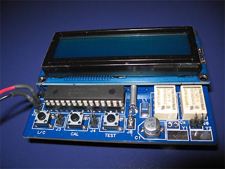 |
Back side 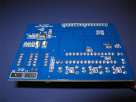 |