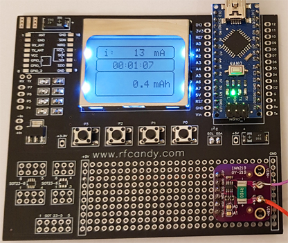
 Arduino Energy meter INA219
How much energy does the SIM800L need to work properly, and can I run it on solar cells?
Arduino Energy meter INA219
How much energy does the SIM800L need to work properly, and can I run it on solar cells? Hardware and schematic
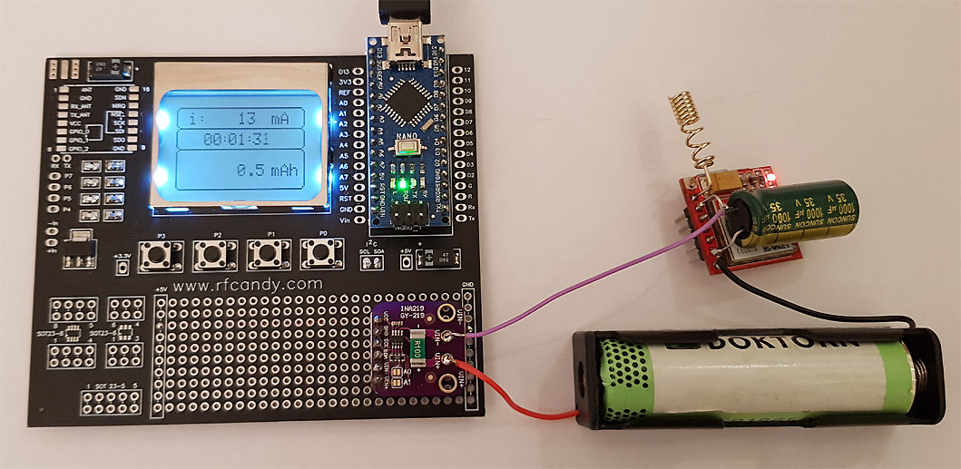
 Order a KIT
Kit include pre assembled board ready to use as energy meter. Unit will have perfect contrast and functionality! |
|
|
Order here |
|