This amplifier will amplify 4000 times and deliver 1W output power. 
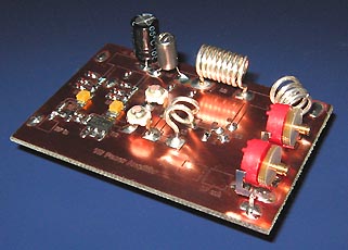
Ipod Stereo FM transmitter with 1W output power.
Many people prefer to listen to their own music (or voice) on radio.
This project explain how you can build and connect a powerful 1W amplifier to your FM transmitters.
A perfect solution for those wishing to listen to their favourite tunes in the car, house, garden,
school, campus, party, you name it....
Why not share your music with every one else in your city!
This project is also made as a KIT, more details below.

This is strictly an educational project explaining how an amplifier works.
This project may well be illegal to use, but that is up to YOU to investigate.
All contribution to this page are most welcome!

Background
Today it is very popular to connect the Ipod, MP3 or CD player to some kind of FM transmitter.
The transmitting signal can the be picked up by any FM radio receiver. Most often used in cars.
The problem with most FM transmitter is that they have very weak signal and short transmitting range.
Some units are so bad that even when they are placed really close to the receiver, you barely receive the signal.

This photo show the Stereo FM transmitter. Wire to left is for audio input and wire to right is the modified RF output signal. 
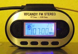
The transmitting signal is just a few micro watt and that is no good, right :-)
This project will change that dramatically.

Features:
After 6 month of search, I finally found the "holy grail". A no-name commercial quality FM stereo transmitter,
which was capable to work with an amplifier. The feature of the transmitter is:
  • Stereo transmits on FM channels 87.5 MHz-108.0M Hz (0.1MHz increments)
  • Distorsion < 3%
  • Signalto noise > 45dB
  • Memorize up to 4 FM frequencies
  • Features low-battery LED indicator
  • Operating Range: 20-40 feet
  • (Requires 2 AAA batteries (38mA))
  • Audio Frequency Range: 20Hz to 20Khz
  • Low battery detect function
  • Temperature guage
  • LCD clock display
  • Blue display light


  • Just plug the MP3-Europe transmitter into the headphone jack of your Zen Creative, iRiver, Sony mp3 players, PDA, CD, cassette player, PC, or laptop.
    Tune your car stereo or receiver to any clear FM frequency, and enjoy your mp3 music experience.

    What is inside the FM transmitter ?
    This section will show and explain what is inside the transmitter.
    You do not need to make any modification or complex surgury of the transmitter to sniff out the RF, so don't worry. I will later explain in details how to sniff out the RF

    The plastic cover was assembled with a few screws and was very easy to open.
    Inside I found a 2 side PCB with lot of components and a very flashy blue display.

    The photo at right show you the backside of the PCB, where most parts are to be found. In the middle of the PCB you will find the main controlling CPU.
    At top left you will find the main crystal of the unit. It took me quit some time to figure out where to find the RF signal.

    Backside of the PCB
    This PCB is NOT a general PCB for FM transmitters.
    Every FM transmitter brand has it's own PCB and construction.
    With help of a Spectrum Analyzer, I could trace the main oscillator, buffer transistor and finally the output booster transistor.

    The good side with a Spectrum analyzer is that you can easy find RF signals and you can also measure the output RF power.
    The downside with a Spectrum Analyzer is that they are very expensive to buy.

    A photo of another PCB of equal transmitter.
    Backside of the PCB
    Easiest way to find the RF out is to follow the GND trace of the ear plugs. The rf signal share the same wire as the ground, but they are separated by a ferrite bead (FB) or sometime with an inductor.
    A ferrite bead will act as high impedance for the RF so there will be no RF short circuit to ground.
    At this PCB, I have a small capacitor in serial wich gives a good place to pick out the RF.
    You can also find the buffer amplifier and the VCO transistor.

    At the bottom of this page, you will find info how to order your own KIT for 1W Amplifier and FM transmitter.

    Spectrum Analyzer Agilent HP 8558B Spectrum Analyzer  plot
    Let's have a look at the RF output signal from the FM transmitter.
    The pic at right show you the spectrum signal with very narrow bandwidth.
    It is not overtones you see, no it is the main peak and the 19kHz pilot tone for stereo separation.
    What is interesting to see is the output power, which is about -6dBm.
    -6dBm is about 250uW....not much..

    No wonder why the transmitting range is so bad, specially when there is no proper antenna.
    250uW from this unit gives a transmitting distance less than 5 meters.

    The amplifier in this project will boost the low RF signal in 3 stages, until we reach +30dBm = 1W.
    With +30dBm and a proper antenna you will be able to transmit up to 10.000 meters.


    Click here to view a larger schematic 
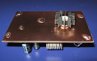
Hardware and schematic
    The schematic show you a RF amplifier with very high gain. The feeding RF signal enter C9 to transistor Q1 which has a self biased working point. The gain and working point is set with the two resistors R1 and R2.
    FB1, C5, C6 works as filter for rejecting RF to power line. Q1 has a gain about 15dBm. The output signal can be found a the collector which then enter a second amplifier stage Q2. This stage also has a self biased working point.
    The gain is set by the resistors R3//R4 and R5//R6.
    Why do I have 2 parallel resistors like that?
    It is because I want to be able to change the gain of the amplifier. On the PCB below you will see that I only have 2 pads for the resistors. When I want to resistors I solder the two resistors R5 and R6 on top of each other and the same with R3 and R4.

    I advice you to start building without R3 and R5 and test the unit. If you want you can then add R3 and R5 later to obtain max gain of this stage.
    Q2 has a gain of 12 dBm. FB2, C7, C8 works as filter for rejecting RF to power line.

    The last amplifier stage is based around the transistor 2N3866. This transistor has low input impedance.
    I match it by using 2 capacitors (C11, C12) and the inductor L1 to about 50 ohm. The transistor has an output impedance match, (C13, C14, and L3) to get best performance for an 50-75 ohm antenna.

  • The inductor L1 is made by a wire 2 turns with 5mm diameter.
  • The inductor L2 is made by a wire 7-9 turns with 6.5mm diameter.
  • The inductor L3 is made by a wire 4 turns with 6.5mm diameter.


  • L4 is a Axial Lead Bead, which reject RF very good and has low resistance. You can use almost any choke or large inductor for L4, it is not a critical component.
    The FM transmitter require 2 AAA batteries and consume about 38mA.
    To get rid of batteries, I have added a voltage regulator IC1, to the PCB which deliver 3.3V to the FM transmitter unit.

    PCB
    Click on the picture to enlarge.
    ipod1.pdf PCB file for Ipod Stereo FM transmitter with 1W output power (pdf).

    Above you can download a (pdf) filer which is the black PCB.
    The PCB is mirrored because the printed side should be faced down the board during UV exposure.
    To the right you will find a pic showing the assembly of all components on the same board.
    This is how the real board should look when you are going to solder the components.
    It is a board made for surface mounted components, so the copper is on the top layer.

    Grey area is copper and each component is draw in different colours all to make it easy to identify for you.
    The scale of the pdf is 1:1 and the picture at right is magnified with 4 times.
    Click on the picture to enlarge it.

    Photo of my Amplifier
    Good grounding is very important in a RF system. I use bottom layer as Ground and I connect it with the top layer at five places (via-holes) to get a good grounding.
    Drill a small hole through the PCB and solder a wire in each via-hole to connect the top layer with the bottom layer which is the ground layer.
    The five via-holes can easy be found on the PCB and in the assembly pic at right, they are labelled "GND" and marked with red colour.

    As you can see on the right photo, the transistor is placed on the backside of the PCB. The reason for this is to add space for cooling the transistor.
    When the transistor get warm (HOT), the gain will drop dramatically and the transistor will finally break.
    There are many ways to cool a TO39 case. You can add a block of heat sink or mount any metal to lead away heat. Fan works good too.
    The cooler you get it, the better it will perform.

    Important:
    Remember that the case of the Q3 is the collector and has direct connection to +12V DC.
    This case must NOT come in contact with the ground plane (GND) or any order parts of the PCB.
    At the right photo below, you can see that I have soldered Q3, 3-5mm above the ground plane.


    Preparing BCP for transistor Q3:
    The picture below show a vertical cut through the PCB.
    Here you can see the Top side which has the strip line connections to all the parts and to the transistor legs Base and Collector.
    You can also see the ground plane on the other side of the PCB.
    After I have drilled the thin hole for the transistor legs, I use second larger drill (3mm), and drill a little bit into the ground plane.
    The larger 3mm drill remove the copper around the hole and you will have no electric contact between the ground plane and the legs of the transistor.
    The procedure must be done for both the Base-leg and the Collector-leg. Since the Emitter-leg is already connected to ground, this hole doesn't need to be modified.
    As you see of the picture below, the transistor leg is connected (soldered) to the pad, but the leg has no connection to the ground plane.


    Soldering and testing:
    The soldering of this unit is pretty basic.
    Connect all parts and make sure you have no soldering bridges on the PCB. soldering wick and rosin are good tools to have handy while soldering.
    When testing the amplifier I advice you to use a 50 ohm dummy resistor as load or a proper antenna (more info about antenna below).
    Make sure you use a non-inductive resistor. Before you switch on power you should set the variable capacitors C13 to max capacitance and C14 to min capacitance.

    DC testing:
    To make sure that both transistors Q1 and Q2 has good working point I advice you to measure the DC voltage at the junction R1 - FB1 and R4 - FB2.
    I measured with NO input RF signal:

    DC volt FB1 = 3.7 to 3.9 V
    DC Volt FB2 = 7.1 to 7.4 V

    Now your unit is ready to be tuned for best performance!

    This photo show where to connect to the FM transmitter PCB. 
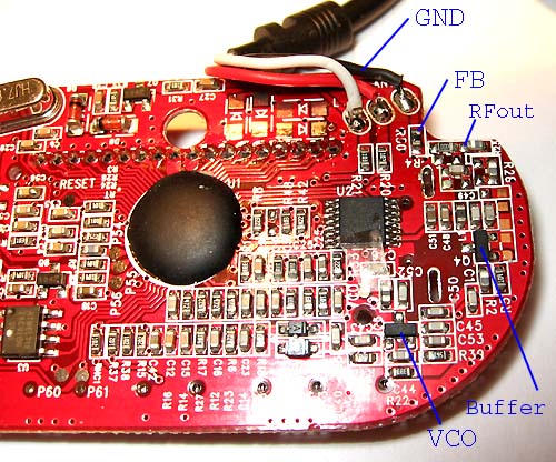
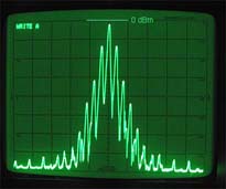
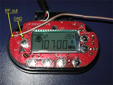
Sniffing RF from the FM transmitter PCB
    The photo at right, show you the front of the FM transmitter when the case is removed with 2 screws.
    To the left side you will find 2 soldering pads. left pad is the RF out and the right pad is ground. Very easy to locate.
    A thin coax cable is connected from the pads to the 1W amplifier. Since I use a thin coax I can easy assemble the case back to the FM transmitter. You can also skip the case and mount the FM transmitter PCB into your own box and connect external buttons. Very high cool-factor :-)

    I must ephesise that the two connection pad only exist on the FM transmitter PCB I can support.
    If some other FM transmitter is used, i can not tell you where to connect or if it will work properly with correct RF levels.


    Antenna
    The antenna part of a transmitter is very important.
    Any piece of wire will act as antenna and radiate energy.

    The question is how much energy is radiated?
    A poor antenna may radiate less then 1% of the transmitted energy, and we do not want that !

    There are so many homepages describing antennas so I will only give you a short version here.

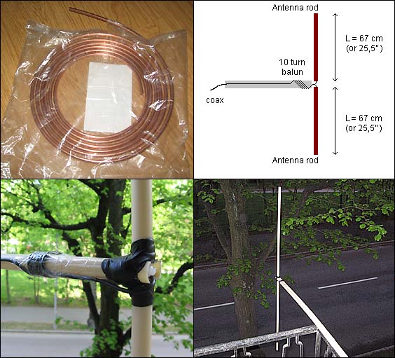
    The antenna is a tuned unit itself and if it is not properly made, the energy from the transmitter will be reflected (from antenna) back into the RF unit and burn up as heat. Lot of noise will be produced and eventually the heat will destroy the final transistor.

    Sine most energy is reflected back into the transmitter, you will not be able to transmit specially long distance either. What we want is a stable system where all energy leaves the antenna out into the air.
    A proper antenna is not difficult to build. I suggest a dipole antenna. It is easy to build and work very well.

    The basic dipole antenna is of the simplest design, yet most used antenna in the world. The dipole claims a gain of 2.14dbi over isotropic source. The centre conductor goes to one leg of the dipole and the outer conductor (braided wire) goes to the other. The dipole antenna impedance ranges from 36 ohms to 72 ohms depending upon the transmission line used, with 52 ohms as the norm. Separation of the centre and outer conductor where the coax or other feedline connect should not extend beyond 1" inch. Always mount the dipole at least it's total length, or greater height above the ground or building for best results.

    Frequency versus length
    A dipole is cut to length according to the formula l=468/f(Mhz). Where l is the length in feet and f is the center frequency. The metric formula is l=143/f(Mhz), where l is the length in meters. The length of the dipole antenna is about 80% of an actual half wave at the speed of light in free space. This is due to the Velocity of propagation of electricity in wire versus electromagnetic radiation in free space.

    Dipole with Baluns
    A dipole antenna is called to be symmetrical. The coax cable is unsymmetrical.
    You should not connect an unsymmetrical coax directly to the symmetrical dipole antenna because the outer shield of the coax will act as a third antenna rod and it will affect the antenna (and antenna pattern) in bad ways.

    You can say that the coax acting as a radiator instead of the antenna. RF can be induced into other electronic equipment near the radiating feedline, causing RF interference. Furthermore, the antenna is not as efficient as it could be because it is radiating closer to the ground and its radiation (and reception) pattern may be distorted asymmetrically. At higher frequencies, where the length of the dipole becomes significantly short as compared to the diameter of the feeder coax, this becomes a more significant problem. One solution to this problem is to use a balun.

    So what is a balune then?

    A balun, pronounced /'bćl.?n/ ("bal-un"), is a passive device that converts between balanced and unbalanced electrical signals, such as between coaxial cable and antenna.

    Several type of baluns are commonly used with dipoles - current baluns and coax baluns.
    Two simple balun are ferrite and inductive coiled cable, see pic at right.

    The inductive coiled balun is simple to make.
    A few turns of the cable around a tube will do the job.(It doesn't need to be a ferrite core)
    The balun should be placed close to the antenna.
    Some links:
    What is a Balun, and Do I Need One?
    Balun 1
    Balun 2
    Balun 3
    Balun 4

    By now, I think your brain feels pretty "unsymmetrical"... Take a break with a good cup of coffee or tea.

    Tuning and testing
    Simple testing unit which measure the filed strength. There is four capacitors C11 to C14 you have to tune for best performance.
    A simple way to test the amplifier is to build an extra dipole antenna and use it as a receiver.
    Take a look at the schematic at right. I use a dipole antenna as receiving antenna and the signal is then rectified to a DC voltage by the germanium diode and the 10nF cap.
    An 100uA -meter will then show the signal strength. A very easy unit to build.
    You can remove the 100k resistor and the OP, and connect the uA meter directly after the diode.
    The unit will not be so sensitive then, but still work good.

    I place the receiving antenna a bit away from the transmitting antenna and tune (C11 to C14) until I reach strongest reading from the 100uA meter. If you get too strong reading you can add a serial resistor to the uA meter or move it farther away. If you get to low signal you can use the OP and set high gain with the 10k pot.
    You can also add a (MSA-0636 Cascadable Silicon Bipolar MMIC Amplifiers) between the antenna and the rectifier.

    Of course you can tune your system with a dummy load or wattmeter, but I prefer to tune my system with the real antenna connected.
    In that way I tune the power amplifier and measure the real field strength with my second antenna.

  • One basic rule during tuning is to measure the main current to the amplifier.


  • When the transmitter is close to match (tuned correct) the main current starts to drop, and you will still have high field strength. The field strength can even increase when the main current drops. Then you know the match is good, because most of the energy is going out of the antenna and not reflected back into the amplifier.

    How far will it transmit?
    This question is very hard to answer. The transmitting distance is very dependent on the environment around you. If you live in a big city with lot of concrete and iron, the transmitter will probably reach about 400m. If you live in smaller city with more open space and not so much concrete and iron your transmitter will reach much longer distance, up to 3km. If you have very open space you will transmit up to 10km.
    One basic rule is to place the antenna at a high and open position. That will improve your transmitting distance quit a lot.

    Very ruff estimation of transmitting distances.

    How to build a dipole antenna in 45 minutes
    I will explain how to build a simple but very good dipole antenna, and it only took 45 minutes to build.
    The antenna rod is made of 6mm copper tube I found in a shop for cars. It is actually tubes for the breaks, but the tube works great as antenna rods.
    You can use all kinds of tubes or wire. The benefit of using a tube, is that it is strong and the wider tube diameter you use, the wider frequency range (bandwidth) you will also get. I have noticed that the transmitter gives highest output power around 104-108 MHz so I set my transmitter to 106 MHz.

    The calculation gave the rod length of 67 cm. So I cut off two rods at 67cm each. I also found plastic tube to hold the rods and to give it a more stable construction.
    I use one plastic tube as boom and a second to contain the two rods. You can see how I used black duct tape to hold the two tubes together.
    Inside the vertical tube are the two rods and I have connected a coax to the two rods. The coax is twisted 10 turns around the horizontal tube to form a balun (rf choke) to prevent reflections. This is a poor mans balun and lot of improvement can be done here.

    I placed the antenna on my balcony and connected it to the transmitter and turned on power supply. I live in a medium city so I took my car and drove away to test the performance. The signal was perfect with crystal clear stereo audio. There are many concrete building around my transmitter which affects the transmitting range.
    The transmitter worked up to 5 km distance when the sight was clear (could not obtain line-in-sight). In city environment it reached 1-2km, due to heavy concrete.
    I find this performance very good for a 1W amplifier with an antenna which took me 45 min to build. One should also take in account that the FM signal is Wide FM, which consume much more energy than a narrow FM signal does. All together, I was very pleased with the result.

    This antenna took me 45 minutes to build and gave pretty good performance

    Antenna testing and measuring
    The pic below show you the performance of this antenna.
    Thanks to a complex antenna analyser, I have been able to get a plot of the antenna performance.
    The red curve show the SWR and the grey show Z (impedance). What we want is a SWR of 1 and Z to be close match to 50 ohm.

    As you can see, the best match for this antenna is at 102 MHz where we have SWR = 1.13 and Z = 53 ohm.
    I did run my antenna at 106 MHz, where the match is worse SWR = 1.56 and Z = 32 ohm.
    Conclusion: My antenna was not perfect for 106 MHz, I should re-run my filed test at 102 MHz. I will probably get better results and longer transmitting distance.
    Or I should make the antenna a bit shorter to match the frequency 106MHz.
    (I am sure I will come back to this topic with more measurements and tests, although I am impressed of the transmitter performance even when the antenna was poor.)

    Frequency
    SWR
    Z (imp)
    102.00 MHz
    1.13
    53.1
    106.00 MHz
    1.56
    32.2

    Measurement of the dipole

    Kit
    All component for "Stereo FM transmitter with 1W output power" are included in the KIT (Click here to download component list.txt).

    Frontside of the PCB, with a blue LED light
    The kit cost = 45 Euro
    and includes all components + PCB.
    1 pcs
  • PCB (etched and drilled)
  • 1 pcs
  • MRF9411LT1 (NPN) smd
  • 1 pcs
  • BFG193 (NPN) smd
  • 1 pcs
  • 2N3866 1W driver (hole mounted)
  • 1 pcs
  • LP2981 smd +3.3V generator
  • 4 pcs
  • Ferrite bead BK1608LM182-T smd (FB1, FB2, FB3, FB4)
  • 2 pcs
  • Inductor 10uH smd (L5, L6)
  • 1 pcs
  • Axial Lead Bead (L4) hole mounted
  • 1 pcs
  • Silver Inductor Wire (L1)
  • 1 pcs
  • Silver Inductor Wire (L2)
  • 1 pcs
  • Silver Inductor Wire (L3)
  • 2 pcs
  • 3.3pF smd (C9, C10)
  • 2 pcs
  • Variable capacitor 6-60 pF (C11, C12)
  • 2 pcs
  • Variable capacitor 9-120 pF (C13, C14)
  • 9 pcs
  • 100nF smd (C2, C3, C4, C5, C6, C7, C8, C15, C16)
  • 1 pcs
  • 220uF hole mounted (C1)
  • 2 pcs
  • Resistors 100 ohm smd (R3, R4)
  • 1 pcs
  • Resistors 330 ohm smd (R1)
  • 3 pcs
  • Resistors 10k smd (R2, R5, R6)
  • 1 pcs
  • Thin 50 ohm Coax cable (to connect transmitter to amplifier)
  • 1 pcs
  • soldering lead (Extra thin)

  • Order here


    Final word
    In this part, I describes a very powerful FM transmitter with an 1W amplifier.
    The performance and audio quality of this little unit really surprised me.
    I also find this unit very easy to build, even for people with short experience of soldering.
    You can always mail me if there is anything unclear.
    I wish you good luck with your projects and thanks for visit my page.


    Back to main Page  |  Contact Me  |  Cheap components

    Copyright © Last modified on 9 April 2007.