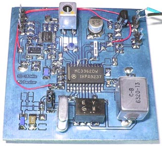
This picture show my experimental PCB for testing the perfomance of the MC3362 MC3362 FM Receiver
This homepage is dedicated to my experience of MC3362 FM receiver.
For long time I have had need of a good FM receiver.
This homepage is not final, it will grow with new experiences.
I will share my practical experiments and measurements about this circuit.
In that way, you will not need to make same mistakes as me.
I also hope you will find valuable information for your own projects.
Please put on your saftybelt and enjoy the ride.
All contribution to this page are most welcome!

Background
Before I go into details and measurements about the MC3362, I will blurr quit a lot about receivers in general.
If you are new to radio this section will probably give you good perspective how it all works.
If you are old in the game you can probably find something to enlighten me about.
To fully understand how important all parts in the MC3362 are, you must understand the purpose of each part.
Before reading, please boost yourself with some redbull drink, coffee or other 2-aminoethanesulfonic acid.

Basic receiver
To fully understand MC3362, we need talk a bit about how a basic radio receiver works.
Blockdiagram of a basic receiver
The figure above is a simplified block diagram of a "Superheterodyne receiver" which uses the principle of frequency mixing or heterodyning,
to convert the received signal to a lower "intermediate" frequency.
To the left you find the antenna which is connected to a mixer. Below the mixer you will find an oscillator.

The mixer will mix the input RF signal with the oscillator frequency.
The output product from a mixer will be the sum and the difference frequency also called Intermediate Frequency (IF).
(A lot of other product frequencies will be produced, but non of our interest.)

Example:
Let's say we set the oscillator to 155.7 MHz. If the output from the mixer should be 10.7MHz, the rf input to the mixer will be the difference frequency 155.7 - 10.7 = 145 MHz…great!

So how about the sum frequency of the mixer, I mentioned above?

Well, 155.7 + 10.7 = 166.4 MHz…Oups….

Mirror frequencies This means that our little receiver will actually receive two stations 145MHz and 166.4 MHz at the same time. Two at the same time is not fun when it comes to radio receivers.
The unwanted frequency (166.4MHz) is called image frequency. The unwanted mirror frequency is removed by the antenna input filter (pre-selector).
In the receiver above we wish to receive at 145 MHz, so the antenna filter will be tuned to 145 MHz and attenuate 166.4 MHz.

There are several standard IF frequencies and some common used are 21.4MHz, 10.7MHz, 455kHz and some higher frequencies as well. The reason of using a standard IF is to be able to standardise the following amplifier electronic and filters. To each standard IF exist several types of filters and crystals. The filter will reject all other frequencies except the wanted IF which will pass through the filter to next stage. The electronic in the amplifier is also designed to match the frequency.

After the filter you find an amplifier which will amplify the weak RF signal. After the amplifier you will find a demodulator which brings out the audio from the FM or AM signal.

Conclusion :
With an oscillator and a mixer you will actually down convert RF frequencies to a lower Intermediate Frequency (IF). The IF will pass a filter to an amplifier and finally a demodulator will recover the audio.

Note:
If you measure the frequency from the oscillator with a frequency counter you will read 155.7MHz, but in reality you will receive at 145 MHz.
Some frequency counters can add or subtract IF frequency and thereby show the correct receiving frequency on the display.


Dual Conversion Circuitry
In a dual conversion receiver you have two mixers generating two IF frequencies. There is also two IF filters.
The main advantage with a dual receiver is that suppression of image frequency is easier.
Since you have two IF filter you will also have better suppression of unwanted signals and frequencies.
Look at figure below.

As you can see from the figure we have added a second mixer, oscillator and IF filter.
The frequency input to mixer 2 is 10.7MHz as we discussed earlier. The oscillator of mixer 2 is at 10.245 MHz (most often a crystal oscillator), but other frequencies can also be used.
The output frequency from mixer 2 will be the second IF of 455 kHz.

10.7 MHz - 10.245 MHz = 455 kHz.

The second IF of 455kHz passes a new filter before it goes to the amplifier.

This leads us to some questions about the filter. What do they do and why are they important?

IF Filters
The main purpose with IF filter is to reject unwanted rf signals and let wanted frequencies pass without attenuation. Look at figure below.

The input to the mixer (antenna side) has a wide band of signals around 145MHz. Some signal are just noise other are close by stations.
The mixer will convert the rf band around 145 MHz down to 10.7MHz with noise other stations and all.

Now, we are only interested in the 10.7MHz, so the IF filter will reject all frequencies outside the filter band.
Most IF filters have very good performance and will attenuate unwanted frequencies really good.
After the filter we have the wanted 10.7MHz signal.

The less unwanted signal that passes the better signal to noise ration we will get, and that means better audio quality and more sensitive receiver.
A dual conversion circuit has 2 IF filters and that means that the rf signal has to pass two IF fitler which will improve the signal even more.

The more narrow filter you have in a receiver from antenna to audio source, the better signal to noise ration you will get. You will also get higher sensitivity of the receiver.

Let's take a look inside MC3362 FM Receiver


The RF signal can be feed into mixer 1 (marked red) by pin 1 or pin 24. In this case pin 1 is used (single input).
At pin 21 and 22 you will find a capacitor and inductor. Together they form an oscillator unit (marked purple). The signal from the oscillator goes to the mixer 1.
At pin 20 you will find a buffered output of the oscillator. This output is used to regulate the oscillator in a PLL system.

At pin 23 you will find the input to a varicap diode. This diode is a part of the oscillator and the voltage to pin 23 will set the capacitance in the varicap which then will affect the oscillator.
You have a voltage controlled oscillator here. Change the voltage at pin 23 and the frequency will also change.

After mixer 1 at pin 19 you find the first IF filter (marked blue). This filter is 10.7 MHz.
The RF signal which will passes the IF filter will come to pin 17 which is the input of mixer 2.

At pin 4 you will find a 10.245 MHz crystal (marked orange) which forms a colpitt oscillator with pin 3.
The 10.245 MHz signal will feed mixer 2 and the product out of mixer 2 end up at pin 5.

At pin 5 you find the second IF filter (marked yellow). This filter is 455kHz.
The RF signal which will passes the IF filter will come to pin 7 which is the input of the main amplifier (marked pink). It is here most of the gain will take place.

Pin 8 and 9 will handle the gain and keep the rf signal to a constant level to the detector (marked light blue).
Pin 10 and 11 will give an output signal (current) how strong the input RF signal was. (Strength meter)

Pin 12 is the LC resonator which brings out the audio from the FM modulated signal. The audio signal comes out on pin 13.


Practical measurements


The picture above show my experiment board. The hart of the board is the MC3362 smd circuit which is very easy to solder.
To the right you find the Quad coil (LC-resonator) which will bring out the audio from the FM signal. At the bottom you find the 10.245 MHz crystal and the 455 kHz ceramic IF filter (black box).
Above the MC3362 you find the 10.7 MHz ceramic IF filter and the L and C part for the main oscillator. At the right top corner is the voltage stabiliser +5V.
At the top left corner you will find the PLL circuit which keep the frequency regulated and locked to desired channel.
Below the PLL is the reference crystal which keep the PLL locked to correct frequency. In this case I use a 16.8 MHz VCTCXO.

The RF inputs to pin1 and 24 at MC3362 go through the PCB to the other side where I can connect my rf generator to make my measurements.

Main Oscillator pin 21-22 (OSC1)
The LC oscillator consist of an inductor and a capacitor and the internal varicap diode pin 23.
The frequency can be set from a few MHz to above 200MHz depending on the external LC-values and the voltage to the varicap diode.

I have used 3 external capacitors 10 pF, 22 pF, 39 pF. By vary the input voltage to pin 23 and the use of external capacitor I have got a good frequency table.
The table below summarise some of my measurement and reach from 78 - 216 MHz

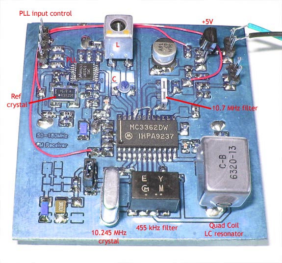
Frequency in MHz, Inductor in this experiment is a smd 68 nH
Input voltage pin 23
No Cap
Cap = 10 pF
Cap = 22 pF
Cap = 39 pF
0 V
131.4
108.8
92.1
78.0
0.5 V
141.1
113.5
94.7
79.1
1.0 V
162.0
123.4
99.0
81.7
2.0 V
188.1
131.2
103.3
83.2
3.0 V
199.6
134.5
104.6
83.9
4.0 V
208.5
136.8
105.4
84.4
5.0 V
216.3
138.6
106.2
84.7

You can of course change the inductor as well. In my picture I have used a CAN-inductor with a tunable ferrite slug core.
The inductance could be changed from 50 to 150 nH which gave me a wide frequency range.
A good advice to you is to use a variable capacitor as I have done in my experiment (see picture above).

The capacitor is 3-20 pF and together with 68nH I could reach :
  • 0V to pin 23 (varicap) and with 20pF (variable capacitor max) I had 94.2 MHz.

  • +5V to pin 23 (varicap) and with 20pF (variable capacitor max) I had 108.7 MHz.


  • When I set the variable capacitor to min:
  • 0V to pin 23 (varicap) and with 3pF (variable capacitor min) I had 124.2 MHz.

  • +5V to pin 23 (varicap) and with 3 pF (variable capacitor min) I had 185.0 MHz.


  • Conclustion:
    If we use a variable capacitor from 3-20 pF and use a 68nH inductor we will be able to reach the frequency range 94.2 to 185 MHz with the PLL voltage 0 to +5V at pin 23.


    Input sensitivity
    According to the datasheet the MC3362 has a sensitivity of 0.6uV at 12dB SINAD and 50MHz.
    Here you can hear how a -110dBm (0.7 uV) 1kHz (Modulation=3kHz) signal sounds when it is feed into the MC3362 input.
    Click here to listen to -110 dBm signal at 50 MHz I have only a simple RC filter at the output.

    Here is the same level -110dBm but at 118 MHz.
    Click here to listen to -110 dBm signal at 118 MHz I have only a simple RC filter at the output.


    More test with a pre-amplifer connected
    Here you can hear how a -122dBm (0.2 uV) 1kHz (Modulation=3kHz) signal sounds when it is feed into a pre-amp connected to the input.
    Click here to listen to -122 dBm signal at 118 MHz I have only a simple RC filter at the output.

    Here is the same frequency but with level -127dBm.
    Click here to listen to -127 dBm signal at 118 MHz I have only a simple RC filter at the output.


    Software
    Test software for controlling LMX2322
    The software display the content of the PLL at the top line. At the bottom line you find the frequency.
    There is 6 hex files to choose from in the zip file mc3362.zip.

  • 168MHref_25khz.HEX use 16.8 MHz reference crystal to the PLL and has stepsize of 25 kHz.
  • 144MHref_25khz.HEX use 14.4 MHz reference crystal to the PLL and has stepsize of 25 kHz. 14.4 MHz Ref crystal with ± 0.1 ppm here!
  • 144MHref_10khz.HEX use 14.4 MHz reference crystal to the PLL and has stepsize of 10 kHz. 14.4 MHz Ref crystal with ± 0.1 ppm here!
  • 10MHref_25khz.HEX use 10.0 MHz reference crystal to the PLL and has stepsize of 25 kHz. 10.0 MHz Ref crystal with ± 0.1 ppm here!
  • 8MHref_10khz.HEX use 8.0 MHz reference crystal to the PLL and has stepsize of 10 kHz.
  • 4MHref_10khz.HEX use 4.0 MHz reference crystal to the PLL and has stepsize of 10 kHz.


  • The frequency can be set from 0 to 999.000 MHz with th 25kHz step software and 0 to 327.67 MHz with the two 10 KHz step softwares (limitation due to the small stepsize)
    The frequency is controlled by a rotary encoder.

    Download PIC16F870 program (INHX8M format)
    mc3362.zip PLL control software (the hex file is zipped!).


    Hardware and schematic
    To the right you can find the schematic of the receiver and the display/PLL control unit.

    Click here to view a larger schematic Receiver unit :
    To the left you find the PLL circuit. A 16.8MHz VXTCXO crystal deliver the reference frequency for the PLL.
    At the output pin 5 you find a PLL filter which produce a voltage to the varicap diode at pin 23 of the MC3362 circuit.
    Pin 20 at the MC3362 is the buffered output from the VCO. The signal is feed to the PLL for controlling the frequency of the system.
    The VCO consist of a LC oscillator at pin 22 and 23. The system use 2 ceramic filters 10.7 MHz and 455 kHz.
    A quad coil at pin 12 demodulate the FM audio to pin 13. At pin 10 you find the RSSI output which drive a transistor to amplify the output signal.
    At pin 4 you find the second oscillator of 10.245 MHz. The RF is feed to the input pin 1.

    Click here to view a larger schematic Controller unit
    The unit is pretty basic. A PIC 16F870 control the display and interface for the PLL.
    A rotator is connected to RA0, RA1 to set the output frequency.

    Final word
    This project present my basic experiment with the FM receiver circuit MC3362.
    I do not present any details as pre-amplifier or PCB, since this is a general project about FM receiver.
    I will use this circuit in my coming receiver projects and this project has give me much basic understanding.
    I have also been able to measure the performance of the circuit and I am very happy with the results.


    Back to main Page  |  Contact Me  |  Cheap components

    Copyright © Last modified on 3 Oct 2009.