RF Power Amplifier Module
This project will explain how a S-AV10H TOSHIBA RF
Power Amplifier Module works.
It is a common module which can deliver over 14W with as low as 100-200mW input power.
The system is tuned for 50 ohm input and output. The frequency can be 150-175MHz.
All contribution to this page are most welcome!
Background
The main reason I build this is because I needed a high power RF unit for testing a new wattmeter.
This gave me a good chance to test my Power module at the same time.
I have some modules from TOSHIBA and this project is very interesting for me,
because I have always been curious about these modules and how they perform.
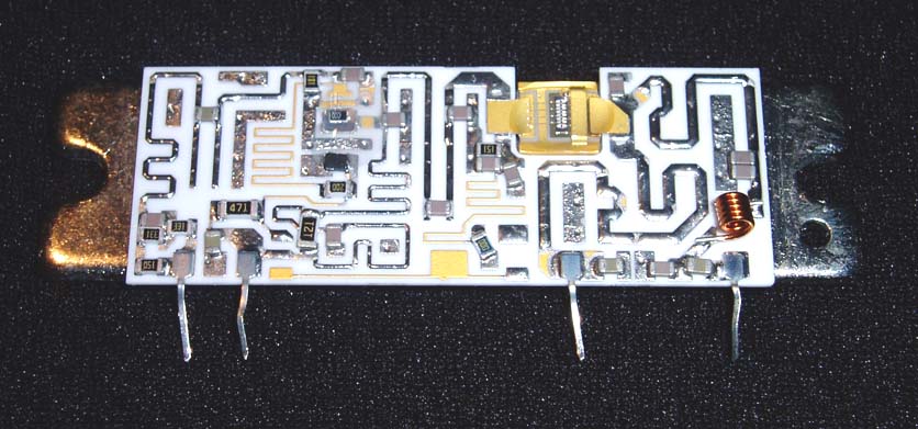
First let's have a look under the hood
This is how the Module looks like. To the left is the power input pin. Then comes power control, main power line and to the right is the output power.
As you see there are quit many components inside and both input and output are matched to 50 ohm.
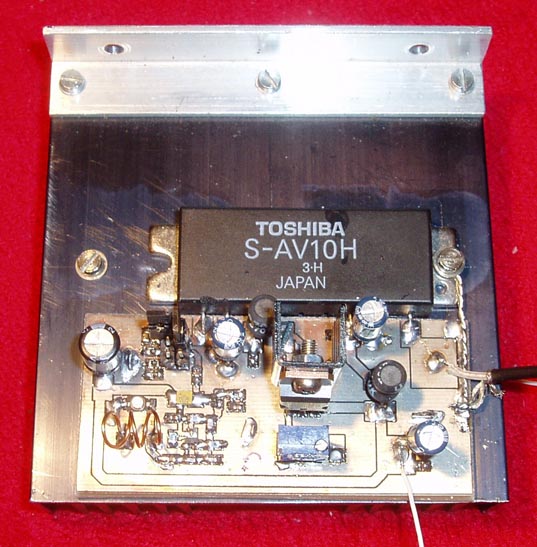
Hardware and schematic
The main part of this project is an oscillator which you will find on the left side.
It is an oscillator based around Q1. L1 and C1 forms the tuned oscillating unit.
The unit can easy be set from 100 to 200MHz by changing C1 and spacing/compressing the aircoil L1.
You can see the air coil at the botoom left corner on the first photo at this page.
Q2 works as a booster and amplify the power to 150mW.
The RF signal then enter the Module at pin 1.
Pin 2 is a power control unit of the Module.
The voltage at this pin will set the output power of the Module.
A voltage stabiliser LM317 is added to generate a variable voltage from 1.25V to 12 V.
You can see it in the middle of the PCB and in front if it is a 10 turn potentiometer (P1).
An inductor blocks RF from the Module to pass out to the power line of the LM317.
Pin 3 of the module is the main power input which also is RF blocked by an inductor.
Theses inductors are not critical in any was, make sure they can handle high currents since the module will consume high current.
Pin 4 of the module is the power output matched to 50 ohm system.
You MUST use a dummy resistor of 50 ohm else you will destroy the module.
Make sure you choose a good resistor which can handle 30-50W.
Make sure you have placed the Module to a heat sink becasue it will be hot.
Measurements
The output power from this module could be set from a few mW to about 18 W by the voltage at Control pin.
The unit was stable down to 145MHz and current was about 2.2A at max output power.
Final word
In this part, I describes a simple power module which can be used for many things.
I am sure I will come back to them and build more.
I think you also find these modules too easy to work with.
They just don't give any challenge building RF projects…*smiling*
 The main part of this project is an oscillator which you will find on the left side.