PLL bug transmitter
This is strictly an educational project explaining how a transmitter works and can be built.
This project may well be illegal to use but this is up to you to investigate.
This frequency of this transmitter is PLL controlled which makes it very stable.
The frequency is programmed in digitally way and can be changed very easy.
Frequency range is about 50 to 150 MHz and the output power 100mW.
All contribution to this page are most welcome!

Background
Stories about spy has always fascinated us ordinary people.
Not to mention the well know agent 007 and all his spy gadgets.
So in memory of Mr Q i dedicate this project to all 007 lovers.
This unit is a bit different from the bugs you have seen on the net.
I bet CIA, KGB, MI5, FBI and DEA would be thrilled to have equipment
which has superior performance and outfit performance as this one...*smiling*

Some construction achievements I wanted were:
  • Simple construction
  • Small outfit
  • Commonly components
  • High performance
  • High frequency stability
  • Good audio quality

  • The output power is about 100mW and most of the time that is too much.
    High output power will consume lot of battery time and that is not good. Most of the time you don't need to transmit long distance.
    The time you want to transmit is more important. The output power is very easy to set and I will explain how to change it to save battery.
    The frequency of this transmitter is programmed digitally by software.
    You find info about the software below. Simple don't you say?
    One difficult part of transmitter is the audio quality. In this case we are going to use a microphone and we want to be able to pick up audio in all kind of environment, therefore I have used a bit different input interface of this transmitter.
    Let's check the schematic and I will explain the function.

    Hardware and schematic
    Click on the pic to see the large schematic. 
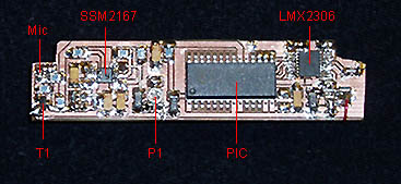
Let's start at the microphone which is a high sensitive microphone found in a cordless phone.
    You can also find them in tape recorders phones and other stuff. The signal is amplified in a transistor and the amplified signal can be found at the collector. The basic problem with audio is that it has a very wide range of energy. The human ear is superior in many ways in this area. We can hear whispering voices at one moment and the next we can hear a jet engine start. This dynamic range is very difficult to copy in electronic way with the same quality as the human ear. Imagine you wish to pick up very silent voices from a room and suddenly someone shoots a gun in that room!
    With silent voices you might need to amplify the audio 1000 times but the loud sound from the gun only need 1 time amplification! So what we wish to have is some kind of automatic gain controller.
    Analog Devices has made a circuit called SSM2167 which is a " Low Voltage Microphone Preamplifier with Variable Compression and Noise Gating"…boy that was long. With simple words you can say it control the amplification of the input audio so the output amplitude is almost constant. I show you with a picture.

    At the input you see two areas of audio.
    The first sound is weaker than the next and the amplitude varies lot.
    At the output you see the same audio (same frequency) but here is the amplitude almost constant.
    The audio input can be either a whisper or a Jet engine. The amplitude of the output signal is still the same size and it is under control. No clipping or distortion of audio.

    So to the bad side of this unit!
    When the input signal is low (almost silent) the circuit amplification is high and the background noise will be amplified much as well. You can see in the figure.
    In my construction I have added a switch (SW1) for the audio source to the transmitter.
    The transmitter can send either the plain audio from the microphone or the compressed audio from the SSM2167.
    If you know the audio level is relative constant and in good level you don't need the SSM2167. You don't have to get the SSM2167 circuit, there are several other on the market. If you wish you can exclude it totally, but as I said the unit will be difficult to use in all environments.
    The function of P1 and P2 are to set the audio level.

    Transmitter
    This transmitter in nothing new, It is basically my FM transmitter.
    You can read all details under my 500mW FM PLL transmitter 88-108MHz project. There are no major changes in the construction.

    Real thing

    This photo show you the upper layer which is the VCO and buffer stage. You can also identify the TXO and antenna connection.


    This photo show you the bottom layer which is the PIC16F870, PLL and SSM2167 circuit.

    Download PIC16F870 programs (INHX8M format)
    The zip file contains several hex files made for different frequencies (80 to 110) MHz.
    bug_100.zip PLL software to FM transmitter (the hex files are zipped!).


    Final word
    This project is explaining how you can build a FM transmitter with great performances.
    I advice you not to use it because it is not legal. You can only use it with a dummy load, not with an antenna.

    You can always mail me if there is anything unclear or need help with PLL frequency software.
    I wish you good luck with your projects and thanks for visit my page.


    Back to main Page  |  Contact Me  |  Cheap components

    Copyright © Last modified on 7 dec 2004.