POCSAG. Post Office Code Standardization Advisory Group
This project will explain what POCSAG is and how it actually works!
You can find many pages about the standard, but what does the signal looks like?
I will show you real measurements and how to decode it.
All contribution to this page are most welcome!

Background
POCSAG is the most widely used protocol for pagers.
The POCSAG standard defines the format used to encode messages and the standards for message transmission.
POCSAG messages are modulated using binary frequency shift keying (FSK) +- 4.5 kHz and the data speed is 512, 1200, or 2400 bits/s. The data is NRZ-coded which means that the higher frequency relates to "0" and the lower frequency to "1".
Here in Sweden you can find several frequencies for POCSAG transmission. The most commonly used system is called minicall and in Sweden you can find it at the frequency 169.8MHz. In the table at the bottom of this page you will find the frequency for different countries.

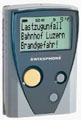
With a simple radio receiver and a POCSAG protocol decoder you will be able to build a unit which can be controlled with just a phone call. I will teach you the protocol and I will also show you real measurements of POCSAG signals.

I have read many POCSAG pages on internet and most of them explain lot but unfortunately there are some major errors which I have fallen into and on this page I will bring them to light and explain them.

Basic POCSAG structure
Before we jump into details I will give you the basic structure of a message.


First part of a POCSAG message is something called preamble signal (yellow box). Se figure above.
The preamble contains at least 576 bits and represents a continuously alternating sequence of 010101...0101.
The purpose of the preamble is for the receiver to identify the incoming of a POCSAG signal and as a synchronisation pattern for the data decoding of batches.

Following the preamble the actual data information are transmitted in batches (green boxes).
Each batch being 17 x 32 bit or 544 bits long. Below i will explain the details of the batches.
I will also show you some oscilloscope capture of the real preamble signal, synchronisation codeword and batch signals.

Batches
Lets focus on the structure of the batches, shall we.


Each batch starts with a 32 bit synchronisation codeword with a fixed content (light blue box).
The 32 bit looks like this : 01111100110100100001010111011000 and in hex it is 7CD215D8.
After the synchronization codeword comes 8 frames (pink colour frame 0 to frame 7).
Each frame is 2 * 32 bit long.

Frame
Lets focus on the structure of the frame, shall we.


Inside each frame you have 2 * 32 bits equal to two codeword. So what is a codeword?
There is two types of code words: Address and Message. Both are 32 bit long.
The address codeword always starts with a "0" (green box).
The message codeword always starts with a "1" (green box).
I explain in more details below.

Address codeword:
The address codeword always starts with a zero and then comes 18 address bits (bit 2 to 19) Receiver Identity Code (RIC).
The RIC is 21 bits so the 3 missing bits comes from the frame number in which the address codeword was sent.
Remember you have 0 to 7 frames equal to 3 bits. Totally you will get 21 bit.
Example: if the address codeword appear in frame 4 the last 3 bit is "100" equal to 4.
The RIC address forms a 7 digit decimal number which uniquely identifies each pager.
The RIC is programmed into each pager before it is sold.
Function bits 20 and 21 allow the pager to identify POCSAG messages from four different paging sources (not important to know).
Bits 22 to 31 are used to provide error detection and correction.
The last bit is parity bit which provides even parity.

Message codeword:
The message codeword always starts with a one.
Bit 2 to 21 (20 bits) forms the message. There are two message forms:
  • Numeric Message Format
  • Alpha-Numeric Message Format
  • I will explain them i details later, but for now you just need to accept that you got 20 bits for message information.
    Bits 22 to 31 are used to provide error detection and correction.
    The last bit is parity bit which provides even parity.

    As you might understand 20 data bits is not enough to form long messages so how does it work ?
    The following frames 1 to 7 will be message codewords and continue the message until the end of the message.

    An example will clear out the sequence of a message.
    The address codeword can appear in any frame but in this example I put it in the first to make it simple.

  • First comes the preamble signal alternating sequence of 010101...0101.
  • Then comes batch 1 and it starts with a 32 bit synchronisation codeword.
  • The first codeword (32 bit) of frame 0 will carry the uniquely address of the pager to call.
  • The second codeword (32 bit) of frame 0 will carry the message.
  • The message can continue in frame 1 to frame 7 and even over to batch 2 and so on.

  • Example of decoding a message
    I have capture a message and my windows program POC32.EXE gave me the info below.
    I also captured the data codewords for the same message.
    Let's have a look together, shall we.

    Time Source Bit/s Address Function Message
    2003-10-16 18:18 COM 1200 1238681 0 (Num ) 1724

    Below you will find the POCSAG data in 32 bits (one codeword).

    First line show you the last part of the Preamble.
    The second line is the synchronisation codeword.
    Then comes the frame 0 to frame 7. As you can see frame 0 is not used and therefore filled with an idle codeword.
    The idle codeword is a reserved codeword whose purpose is to fill the batches. It is represented in binary form as:
    01111010100010011100000110010111 = $7A89C197
    At frame 1 you will find an address codeword (pink colour). Remember I told you earlier that the last 3 bits comes from the frame number and in this case it is 001 equal to frame 1. So the total address is 100101110011010011001 = $12E699 = 1238681 dec
    The second codeword of frame 1 is a message codeword since it starts with a "1".
    The data is marked green and is 1000 1110 0100 0010 0011 = 1724 _
    A bit down you find how to decode Numeric Message Format.
    Frame 2 to frame 7 is also filled with idle codeword $7A89C197.

    Now, lets check with the message we received: At address 1238681, the text 1724_ should appear and so it does.... Great!

    10101010101010101010101010101010 Preamble
    01111100110100100001010111011000 $7CD215D8 synchronisation codeword
    01111010100010011100000110010111 Frame 0 $7A89C197
    01111010100010011100000110010111 Frame 0 $7A89C197
    01001011100110100110011000000011 Frame 1 address $12E699 = 1238681 dec
    11000111001000010001111000000010 Frame 1 1724_
    01111010100010011100000110010111 Frame 2 $7A89C197
    01111010100010011100000110010111 Frame 2 $7A89C197
    01111010100010011100000110010111 Frame 3 $7A89C197
    01111010100010011100000110010111 Frame 3 $7A89C197
    01111010100010011100000110010111 Frame 4 $7A89C197
    01111010100010011100000110010111 Frame 4 $7A89C197
    01111010100010011100000110010111 Frame 5 $7A89C197
    01111010100010011100000110010111 Frame 5 $7A89C197
    01111010100010011100000110010111 Frame 6 $7A89C197
    01111010100010011100000110010111 Frame 6 $7A89C197
    01111010100010011100000110010111 Frame 7 $7A89C197
    01111010100010011100000110010111 Frame 7 $7A89C197
    01111100110100100001010111011000 $7CD215D8 synchronisation codeword
    01111010100010011100000110010111
    01111010100010011100000110010111
    0...............................

    Numeric Message Format
    The numeric message standard uses a 4-bit character set from which to generate messages. Message codewords have a 20 bit message capacity, which means that each codeword contains 5 numeric characters. If a message codeword is not completely filled with data, the remaining characters are filled with the character for a space. Numeric pagers have the capacity to store 20 characters per message, so a numeric message would have a maximum length of 4 message codewords. It should be noted that characters are transmitted in the sequence that they are displayed, but the bit sequence of each character is reversed such that the least significant bit is transmitted first.


    Alpha-Numeric Message Format
    As mentioned, the ISO 7-bit (ASCII) is used for alpha-numeric messages. As in the numeric format, there are 20 bits in each codeword for message data, however, in this format each character is 7 bits. Characters are split between codewords and the last codeword is filled with unprintable characters like end of message , end of text, or null. Null is the only character which can be incomplete.
    POCSAG defines the maximum length for a standard alpha-numeric message as 40 characters.
    However, there are provisions for longer messages which allow up to 80 characters.


    Lot of information don't you say.....so let's have a break now and look at some fun measurements!

    Let's look at some oscilloscope captures


    The capture above show you a complete transmission of a POCSAG messages.
    You can see first the radio signal is quiet and then comes the preamble signal followed with lot of data.
    The hole sequence is about 0.8 seconds and I have no clue what the messages was about ..*smiling*
    As I said before the preamble is continuously alternating sequence of 010101...010, that is why it looks smooth compared to the data part.
    In all the homepages I have read about POCSAG, they claim that the preamble is 576 bits. This is wrong! The preamble is at least 576 bits long. Huge difference don't you think. I also noticed that the length vary lot.

    Let's have a look of the preamble and the 32 bit synchronisation codeword


    The light blue lines in the picture above show you the timing of each data bit. At the top I have written if the data is a "0" or "1".
    Remember the "0" has high DC-level and the "1" has low DC level.
    You can see the preamble alternating 0101.. and then the 32 bit frame synchronisation codeword arrives like
    this : 01111100110100100001010111011000 and in hex it is 7CD215D8.

    One more important thing to notice in this capture is the amplitude of the signal.
    During the preamble phase the amplitude is the same for each period, but when the frame synchronisation and the data arrives the amplitude varies lot. Why is it like that?
    The main reason for this phenomenon is that the receiver has analogue filter at its output that shapes the FSK signal like that.
    It is not good because it will cause trouble when to bring out the data. I will explain the problems more in details and I will show you how to come around it.

    At most POCSAG pages you will read that the audio signal should be taken out from the discriminator of the receiver.
    Yeah great idea you think...I will just go get my soldering tools and then crack open my brand new receiver and
    try to find something called discriminator!!! Forget all that for a moment now and I will explain the problem below.

    Decoding data with schmitt-trigger


    The black line is the POCSAG signal as before.
    The pink line is the output of a smitt-trigger circuit based on a OP and is feed with the POCSAG signal.
    You can easy see that when the POCSAG signal goes higher than the red line at left marked Pos, the schmitt-trigger output (pink) goes low.
    And when the POCSAG signal goes lower than the blue line at left marked Neg, the schmitt-trigger output (pink) goes high.
    This is the common way to recover the data from a POCSAG signal. So, what is the problem then?
    The difficult is to set the scmitt-trigger levels because the amplitude of the POCSAG signal changes depending on the data.
    One more difficult is to find the right amplitude level of the POCSAG signal.

    I have marked a transition "1" in red in the picture and called it "Bad". I will explain what happens there:
    The POCASG audio signal is dropping in amplitude because of the analogue filters in the receiver. Suddenly the level is so low that the schmitt-trigger is changing state and goes high (pink signal). The POCSAG then droops low marked "2" to indicate the true data change.
    As you can see the schmitt-trigger changed at wrong level. The trigg level should have been lower. But if the trigg-level is lower the comming low levels of the POCSAG signal marked "3" will probably not be detected.

    You can see that the bottom peak of "2" is much lower than the bottom peak of "3". The same is it for the positive peaks.
    Conclusion: Since the POCASAG amplitude changes in value depending on the data stream, it is difficult to find the schmitt-trigger levels to recover the data without errors.!

    Do not despair....I have found a way around this problem.

    Windows software
    There is many software for PC which used with receiver to decode the POCSAG signal. One commonly used is POC32.EXE.
    It works great when you have found the right audio level which is not easy! If you want I can mail it to you.

    Decoding data with variable schmitt-trigger


    As I explain above it is a bit difficult to find the schmitt-trigger levels for decoding POCSAG signals without errors.
    I will here describe a way which handles this problems.
    The picture above show you the POCSAG signal as before. The blue line (labelled 128) is the zero line and the sampled signal is totally 256 bits (0 to 255). The red dotted line show you the schmitt-trigger levels and they are symmetrical around the blue zero lines.
    When the POCSAG signal (yellow) passes the red dotted signal the data changes.
    This will work in most cases, but will not give always the right decoding. You can see that in the middle of the picture. The POCSAG signal climb just over the red dotted signal and then it falls back below. In this area the schmitt-trigger level should be higher.
    So therefore I have implemented another schmitt-trigger level (orange dotted line).
    The whole idea is very simple. When data alternate ..1010.. the schmitt-trigger level should be the red line and if the data has the same value for more than 2 bits the scmitt-trigger level should be the orange line. In this way the scmitt-trigger level is variable and dependent of the previous data.
    What advantage will this system give me?
    This system with two scmitt-trigger levels is not so sensitive to the quality of the POCSAG signal and the audio level will not be so critical to set either. The reason I have choose a digital explanation is because a PIC16F870 has an ADC internally and it will handle all the decoding process.
    The hardware and receiver-part will be explained in coming POCSAG project.

    Final word
    This page will give you the basic understanding and information about paging system.
    The system can seem a bit tricky but I think you will get the hang of it.
    To really get a good picture I hope the signal capture I have done, helps you to understand.
    In this page I have not explained the hardware, it will come in the future project where I will build a complete receiver which can be programmable for any address. With that unit you will be able to control anything anywhere with just a phone call.

    You can always mail me if there is anything unclear.
    I wish you good luck with your projects and thanks for visit my page.


    Back to main Page  |  Contact Me  |  Cheap components

    Copyright © Last modified on 1 April 2004.