 Robot Voice
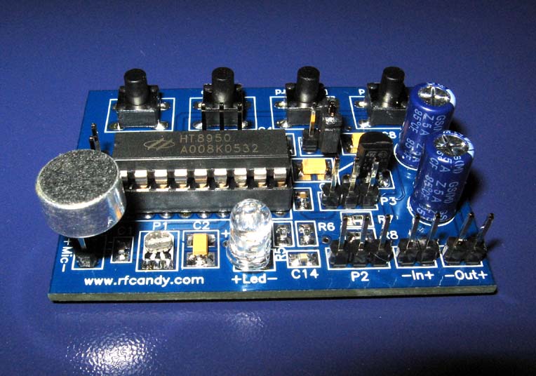
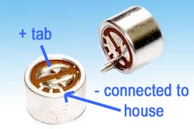
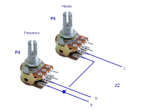
 Hardware and schematic
 Assembly
HT8950 sounds |
|
Robot sound : robot1.mp3 (1.2M)
Robot sound with vibrato : robot2.mp3 (1.2M) Pitch sound : robot3.mp3 (1.2M) |
|
 Order a KIT
which will include all parts |
||
|
The Robot Voice KIT includes all parts, manual, soldering lead, and wick.
|
||
|
Order here Below you can find different options for ordering, click the links for detailed information.
|
||
Front side 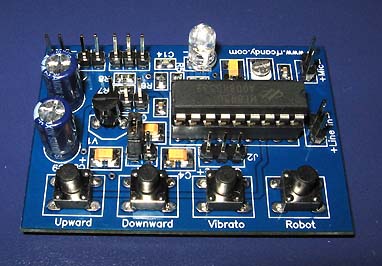 |
Back side 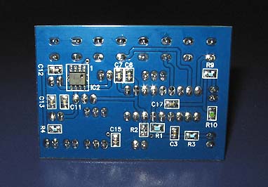 |