To build wireless communication can sometime be quit difficult and you need lot of components.
This transceiver handles it all for you and makes life almost to simple.
All you need to do is to hook up some external components and you have a high speed communication unit.
Features:
Operating Frequency : 868.35 MHz
Sensitivity, 2.4 kbps : -106 dBm
Sensitivity, 19.2 kbps : -101 dBm
Modulation Types : OOK & ASK
Power Supply : 0-4V
Small size
Only 2 inductors, no tuning
Transmitting range 100m
Hardware and schematic
There is not much I can write here. The schematic speaks for itself.
The schematic above is built from the datasheet and works with 2.4 kbps.
The transmitting range was about 100m.
Amplifier 1:
Here is a schematic of a simple amplifier I built to my TR1001.
The output power was +15dBm and I had strong signal at 100m range.
Amplifier 2:
The output power was more than 15dBm and I had very strong signal at 100m range.
I am sure there are many other ways to build PA and I will come back to this and update this page with more examples.
Amplifier 3:
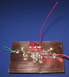
My experiment board
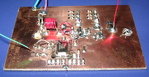
Here is a photo of my experiment board.
You can see the two inductors and the antenna to the right.
There is a few things you should know about the TR1001 circuit.
The data output (pin 7) only deliver low current, so you must not load it down to much.
I used a speaker to listen to the signal, but it loaded the output to much so I barley heard the data pulses.
Best way is to connect the data output (pin 7), to a digital circuit or a processor.
There is 3 data rate mode you can use.
OOK = 2400 bps
OOK = 19200 bps
ASK = 115.200 bps
Each data rate has a Minimum signal Pulse and a Maximum signal Pulse. From the datasheet you can read all details.
If you stay withing in this speed you will have no problem with serial communication.
Soldering:
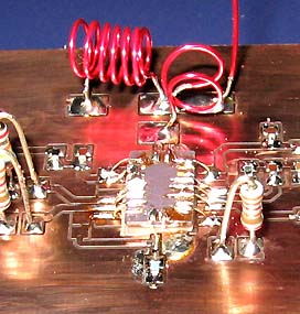
The circuit has pads under the case (not on the side), so it is a bit tricky to solder directly to PCB.
I really advice you to place the circuit up side down and connect the pads with thin wire to the PCB.
This soldering ways is simple to do, and much safer. You can be sure that all pads has been connected.
Photo above show my first soldering directly to the PCB..and it was a bit tricky. The photo at top of the page show how
I solder the circuit up side down.
AV sender using QAM soundcard modem
The TR1001 is perfect to use for sending audio and video.
Take a look at this great software made by Jonti.
AV Rs232 Sender
J-QAM, A QAM soundcard modem
Datasheet
Transmitting distance at 900 MHz
To demonstrate the basic difference in wave propagation of 900 MHz, a quick look at path loss is provided.
As waves propagate out from the transmitter, some attenuation of the signal takes place due to properties of the medium (air in most cases).
Path loss describes this attenuation as a function of the wavelength of the operating frequency and the distance between the transmitter and receiver.
Path loss is derived from the Friis transmission equation and is defined as:
Path Loss = 20 log(4*p*r/λ) dB
where r is the distance between the transmitter and receiver, and λ is the wavelength .
900 MHz transmitters (λ=0.33 meters).
The path loss equation represents path loss (signal attenuation) as a function of distance between the receiver and transmitter and the
wavelength of the operating frequency.
This equation is derived from the Friis transmission equation and is given by:
Path Loss = 20* log(4*p*r/λ) dB (Eq. 1), where
r = distance between transmitter and receiver
λ = wavelength
The Friis transmission equation can be used to represent the path loss as the sum of the other system factors leading to the following equation:
Path Loss = P(t) + G(t) + G(r) - R(s) - F(s) dB (Eq. 2), where
P(t) = transmitted power
G(t) = gain of transmit antenna
G(r) = gain of receive antenna
R(s) = sensitivity of receiver
F(s) = fading margin, (experimentally determined to be 22dBm)
These two equations can be used to calculate the maximum range of RF modules.
- Consider the range of 1W RF module:
= 0.33 meters (for f=900 MHz)
(Eq. 1) Path Loss = 122 dB = 20 * log(4*π*r/λ)
(Eq. 2) Path Loss = 30dBm + 2dB + 2dB - (-110dBm) - 22dBm= 122 dB
This give r = 33 km = 20 miles transmitting range.
- Consider the range of 18W RF module:
This give r = 133 km = 82 miles transmitting range.
Final word
In this part, I describes a very powerful transceiver circuit with few external components.
It can handle all kinds of communication and with an impressive speed of 115.2 kbps.
If you wish to order your own TR1001 or 38H15, you can find it at the component page http://www.rfcandy.com.
You can always mail me if there is anything unclear.
I wish you good luck with your projects and thanks for visit my page.
 TR1001 868.35 MHz Hybrid Transceiver.