Wife Replacer
We all know how difficult is it to tune the output filter of a transmitter for best performance?
Many times I would like to tune my transmitter against a receiver which is far away.
I can't be at two places at the same time! so this gave birth to a new project.
This project consists of a wide range receiver and one transmitter.
Together they will form a unit which will help you tuning your homebrewed transmitter
and substitute your wife at the same time. To good to be true!
It might sound difficult, but give the project a chance, will you?
All contribution to this page are most welcome!

Background
The most difficult part of homebrewing is the tuning part of the transmitters.
How should I design and tune the output filter of my transmitters?
Well, you can use a 50 ohm dummy load and tune the transmitter for best performance.
When you connect your antenna, which probably won't have 50 ohm resistive load and you will lose lot of power.
Okay, you have 100W so what! You will still be able to transmit to your neighbour 1km away.
How about having only a few mW or few Watt! Then you want the energy to go out into the air, don't you?

So, to achieve the best performance of your transmitter you need to measure the receiving strength in a receiver a bit away from your transmitter. Receivers often have an indicator called RSSI (Relative Signal Strength Indicator).
Okay, you put a receiver at next table and you start to tune your transmitter.
You will now see how the receiver RSSI is saturated.
Your receiver is to close to the transmitter!
Let's put the receiver out in the garden then. You will now be running back and forth to your transmitter and receiver, tuning a bit, watching RSSI and so on....well, you could let your wife watch the receiver and scream the result to you inside the house.*smiling*
Your marriage will soon end up in divorce or your landlord will gently ask you to seek professional help! So I have invented this little unit called "Wife Replacer" it will solve all tuning problem. This project might sound as a big one and it is, but it is not a difficult project to build and understand. You will have so much help from this project in the future.
Especially your wife/girlfriend will be happy!
Picture below will explain in a graphical way for you.


Follow this:
You have build a transmitter (blue box).
This transmitter needs tuning to give best performance. 200-500m away from your home in a box is the "Wife Replacer".
The "Wife Replacer" has a receiver (green box) which receive your transmitting signal.
The receiving frequency can be set from 88 to 150MHz (to match your transmitter frequency). The RSSI level of this receiver is measured and a low power transmitter (yellow block) send out the RSSI strength in data format (DTMF tones).
Back at your place, next to your transmitter you have a receiver with display (orange box to the left).
This receiver, receive the DTMF data and show the info on the LED display. You can find the DTMF recevier project here.

Summarize:
When your transmitter (blue box) transmit, the "Wife Replacer" measure the signal strength of your transmitting signal 200-500m away from you, and "shout" back the information to you in a digital format. You can now easy experiment how to build you transmitter for best performance with the true antenna. The "Wife Replacer" is build to work from 88 to 150MHz so, there is a wide range. It can probably go lower and higher as well.

Hardware Details
The "Wife Replacer" is made in two parts:

  • 88-150MHz Receiver

  • 125MHz transmitter


  • Both the receiver and the transmitter frequency is set by a frequency PLL synthesizer. This will give very good stability and easy tuning.
    In this case I use a UMA1015 synthesizer. This synthesizer do have two separate PLL units. I think the easies way to understand the function if you follow the blockdiagram below.


    The basic function:
    At top of the blockdiagram you will find the antenna. The RF signal enter the antenna and is then switched to the receiver (green box).
    The receiving frequency of this box is set by a VCO (Voltage controlled Oscillator) pink box. This VCO can be set from 88 to 150MHz by a voltage (PD) coming from the PLL synthesizer A (left yellow box). The synthesizer also probe the VCO frequency (Fin RX) to regulated the PD voltage of the VCO (pink box). The synthesizer A and B is programmed by a micro controller PIC16F870.

    When the receiving frequency is set, the CPU will measure the RSSI (Relative Signal Strength Indicator) voltage by its internal A/D converter. The RSSI signal is a voltage from 0 - 5V. The CPU will transform the value to 3 digits. The CPU then set the Synthesizer B, so that the VCO (orange box) oscillate at 125MHz. Also here the synthesizer probe the VCO frequency (Fin TX) to regulate the PD voltage of the VCO.
    The output power of this VCO is a few milliwatt. The CPU then switches the antenna-switch so that the antenna is connected to the transmitting VCO. The 3 digits is then sent to the DTMF unit which will modulate the transmitter and the DTMF signals is sent.
    The antenna-switch then go back to the receiver and everything start to repeat again.

    In my schematic below I have also added an audio amplifier to the receiver so you can hear the signal from the testing object.
    I will go into all details later.

    Schematic and Hardware details:
    Let's focus at the receiver part first. The receiver is build around the SA615 circuit.
    This circuit has everything inside, mixer, oscillator, IF amplifier and demodulator.
    The antenna is connected to a LC filter L1 and C1. This filter is a narrow bandpass filter to reject all unwanted frequencies. This filter will also tune the antenna for best performance. The filter can be set to cover the band of 88-150MHz. The rf signal then enter the SA615 and into the mixer.
    Two ceramic filter is connected before the FM demodulator.
    The ceramic filter is at 455kHz and will reject all unwanted frequencies from the mixer.

    The SA615 circuit has an internal oscillator which is internally connected to the mixer.
    The oscillator can be found a pin 3 and 4. The oscillator is a collpit type and the oscillating part is L3 and the varicap diod BB149A. At pin 4 you can find a coil L3 parallel with a capacitor of 3.9pF.

    How to make this oscillator voltage controlled?
    Parallel with the 3.9pF capacitor you will find a varicap diod. The capacitans of this diod is dependent of the voltage over it. So, by applying a voltage to the varicap the internal capacitance will change and so will the resonance frequency. The purpose of the 10pF serie capacitor is to remove the VtuneDC-voltage. By changing the Vtune voltage to the varicap the frequency will slide a few MHz.

    The Vtune is coming from PD1 (pin 3) at the PLL synthesizer UMA1015.
    The voltage is from 0 to +5V and this voltage can change the oscillator frequency a few MHz.

    At pin 3 you will find a resistor Re1. This resistor is added to raise the oscillator current.
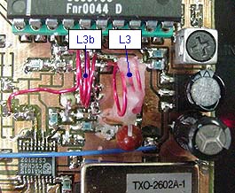
    Pic at right show you the L3 coil. I have put some glue on the coil to make it stable for vibrations. In line with the coil L3 is another coil named L3b. This coil has two turns (no critical dimensions)and it absorb a fraction of the energy from the main oscillator coil L3.

    The purpose of this second coil, is to feed the synthesizer frequency input Fin 1 (pin 6). The frequency inuput is so sensitive that you only need a 1-2 tune coil close to L3 to pick up the oscillation frequency. Other way to probe the oscillator which I used in onther PLL construction is to use a dual gate FET to probe the oscillator.
    I think this new way works better and needs less components.
    By changing the distance from the main oscillator coil L3 and the pick up coil L3b, you can easy adjust the input amplitude to the PLL synthesizer.
    In practical way I advice you to place the L3b close to L3 and see how well it works.
    I had to move L3b (pick-up-coil) a bit away from L3, because it gave to strong signal.
    See the photo at right.

    Purpose of the pick-up-coil:
    What the synthesizer will do with the frequency input from the pick-up-coil, is to regulated the PD 1 voltage until the exact frequency is probed at the Fin 1. The synthesizer then continuently regulate the PD voltage and thereby locks the frequency to the preprogrammed frequency.
    Since the PD1 voltage only can change the frequency a few MHz, you must change (expand/compress) the coil L3 so that the programmed frequency of the receiver can be reached by the PD1 voltage range.

    Example:
    You want to receive at 108MHz .
    The L3 must have an inductance so when the PD1 voltage is in the range of 0 to +5V the oscillator reach 108MHz. The PLL system can now keep the frequency locked. You can probe the PD 1 (Vtune) DC-voltage with a DC meter and see how the voltage is stabilised when the system is locked. If the PD1 voltage is 0V the frequency is to high and you need to compress the coil (equal to add inductance) and if the PD1 voltage is +5V the frequency is to low and you need to space the coil (equal to decreasing inductance).
    When the PD1 voltage is >0 and less than +5V the frequency is locked.

    How to program the receiving frequency?
    The PLL synthesizer has several internal register which set the regulating system so that the oscillator locks to a desired frequency.
    I have made a windows software which handle all the setting of register in the UMA1015 PLL circuit. When the power in turned on in the wife replacer, the PIC will listen 10sec for incoming data. This gives you a timeframe to set the frequency.

    How does it work in reality?
    Connect the cable from the computer to the Wife-replacer. Run the window software and make all the calculation.
    Turn on the power to the wife replacer and you have 10 seconds to press the button "send" in the windows software. It takes less than a second to send the info from the computer to the Wife-replacer. If you want more detailed information about PLL synthesizer and phase comparators, I suggest you read the zipped document at bottom or search the internet for PLL synthesizer.

    Mixer:
    The mixer 1 mix the RF signal with the oscillator frequency and the IF (Intermediate Frequency) is 455kHz. Two ceramic filters damp all other unwanted frequency and the signal then enter the FM demodulator at pin 14. To demodulate FM, the SA615 use a Quad coil.
    The audio signal can be found at pin 9 and the RSSI signal can be found at pin 7.

    125 MHz Transmitter:
    The 125MHz transmitter is based on a dual gate Fet oscillator. Gate 2 is set to DC level for high gain. The oscillating part is coil L2 with the capacitors around it. The varicap BB149A is conneted to the oscillating element via a 10pF capacitor.
    When the voltage over the varicap changes, the internal capacitance will also change and thereby modulate the resonance frequency.
    The second dual gate Fet is working as a buffer. Finally a transistor amplify the power to a few milliwatt. The Re2 resistor of the T1 transistor set the ouptut power. The lower value the more power. The resistor R2 will set the power as well. I use a 18k resistor.
    Parrallel with the L2 coil is another coil L2b.
    L2b is a pickup-coil for the PLL synthesizer (works the same way as with the receiver oscillator I explained above).
    A fraction of the energy in the L2 will be induced in L2b and that is enough to make the UMA1015 circuit work.
    PD2 (pin 17) of the UMA1015 is the Phase-detector-output. The voltage at this pin will be feed back via 100k resistor to the varicap and this regulating system will keep the oscillator locked to 125MHz.

    I don't want this 125MHz transmitter to transmit continuously. My wife replacer measure 1-2 times every second and it takes about 300mS to send the DTMF info. I have therefor let the antenna relay also provide the transmitter with power(TX-power).
    It works like this:
    When the antenna relay draws (means time to transmitt) the relay connect the antenna to the transmitter and two other contacts give power to the TX-power line.

    Wife Replacer Windows Software
    This software will calculate the content of the internal register in the UMA1015. After the calculation the software will send the info to the Wife Replacer via RS232 line.

  • Enter the frequency you wish the oscillator to work at in the left light blue box.
  • Press "Seek Match" button.
  • If every thing is ok press the button "Send" and the UMA1015 in the wife replacer will be receining at your desired frequency.


  • IMPORTANT! Remeber the OSC should be 455kHz above the frequency you wish to receive, since the IF of the receiver is working at 455kHz.

    ALL DETAILS!
    With an example I will explain the software for you!
    When you run the software you will see *** stars at Fin RF1.
    Remove the stars and enter the frequency you want the receiver oscillator to lock at. Let's say you wish to receive at 108MHz, then the receiving oscillator frequency should be set to 108,455kHz. Make sure you use "," and not "."
    I have set the reference frequency to 12,8MHz but you can change that if you have other frequency. When you click the button "Seek Match" the software search for the best divider of register "Prog 1 div" and "Ref div" to set the oscillator frequency.
    Let push the button and see.
    A lot of things happens now!
    First lets look at the top in the Prog 1 div frame (light blue). The software tell you that this divider should be 6287. If you look at the Ref div (green box) you can see that this register should be set to 742. If the register is set like this, you will have an frequency error of 13,48Hz in the oscillator. This is the best match you can get for this frequency. (You will not notice this error in the receiver. When error comes above 1000Hz you might notice distorision).

    Let's check if the calculation are true:
    The referens frequency to the PLL unit is 12800000 / 742 = 17250,67 Hz
    Since the PLL try to keep the two input in phase,we can multiply the reference frequency with the
    divider which gives 17250,7 * 6287 = 108454986,5 Hz (locking frequency of the PLL)

    We wanted 108,455MHz and we got 108,4549865MHz and the error will therefor be -13,48Hz.
    So the calculation seems to be okay.

    Example and detailed information can be found in the "help.txt" file which comes with the software.
    If you want the software you have to mail me and I will send it to you.


    Building and testing
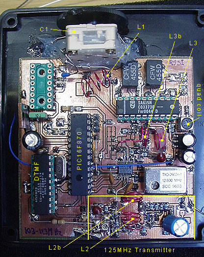
    I first built the receiver and tested that the oscillator worked. In the schematic you will find two input at RB7 (pin 28) and RB6 (pin 27). When RB7 is high the PLL will lock the receiver frequency and keep it locked for testing purpose.
    When RB6 is high the PLL will lock the PLL of the transmitter and feed it with power for testing purpose.
    In normal operation the RB7 and RB6 should be kept low. In my testing procedure I set RB7 high and tested the receiver. I made sure that the oscillator worked and was locked to desired frequency.
    By measuring the Vtune voltage it is easy to see if it works. If the Vtune voltage is 0V or +5V, the frequency is out of locking range. I spaced/compressed the coil until the reading gave a voltage between 0 and +5V.
    With my wireless frequency counter I could assure myself that the right frequency was set.

    I then disconnected pin 20 of the SA615 circuit to its ceramic filter. I feed the ceramic filter with 455kHz modulated signal to test the demodulator. After a succesful test I reconnected pin 20 to the ceramic filter.
    Now it was time to test the transmitter part. I set RB7 to gnd and the put RB6 high. The PIC and the PLL will now go into transmitting mode. TX-power will feed the transmitter and I could check the transmitter oscillator with my wire-less frequency counter to make sure it oscillated at 125MHz. Also here the PD2 voltage should be higher than 0V and lower than +5V to keep the frequency locked to 125MHz.
    By measure the voltage a PD2 (pin17) I could easy space/compress the coil until the PLL locked to 125MHz.
    The two pickup coils (L2b and L3b) didn't need much adjustance to work.
    I had to move the L2b a bit away from L2 because the signal was to strong from L2. After that adjustment it worked perfect.

    Download PIC16F870 program (INHX8M format)
    vf.zip Wife Replacer program (the hex file is zipped!).


    Download Word document about PLL fuction
    plls.zip Basic function of PLL (the doc file is zipped!).

    Final word
    This project is a big project and it is not the easiest one to built.
    I advice you to build it in small blocks and test each of them before you put everything togeter.
    Still I hope this page will give you some inspiration and help to build and understand.

    You can always mail me if there is anything unclear.
    I wish you good luck with your projects and thanks for visit my page.


    Back to main Page  |  Contact Me  |  Cheap components

    Copyright © Last modified on 29 oct 2003.