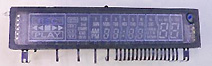
 Vacuum Fluorescent Display (VFD)
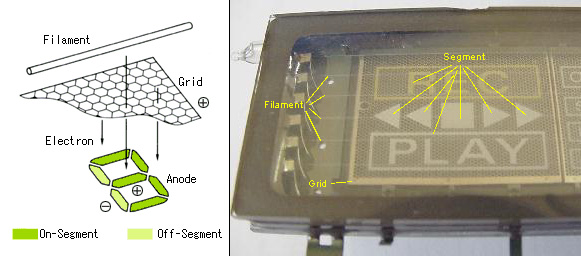
 The VFD is composed of three basic
electrodes; the Cathode (Filaments), Anodes (Phosphor) and Grids
under a high vacuum condition in a glass envelope.
The Cathode consists
of fine tungsten wires which are coated with alkaline earth metal oxides
which emit electrons.
The Grids are a thin metal mesh which
control and diffuse electrons emitted from the Cathode.
The
Anodes are conductive electrodes on which the phosphor is printed to
indicate characters, icons or symbols.
Electrons emitted from the
Cathode are accelerated with positive potential applied to both Grid and
Anode, which upon collision with the Anode excites the phosphor to emit
light. The desired illuminated patterns can be achieved by controlling the
positive or negative potentials on each Grid and Anode. This voltage can
be as low as 10VDC.
 Fig.1
Basic VFD Structure
Fig.1
Basic VFD Structure