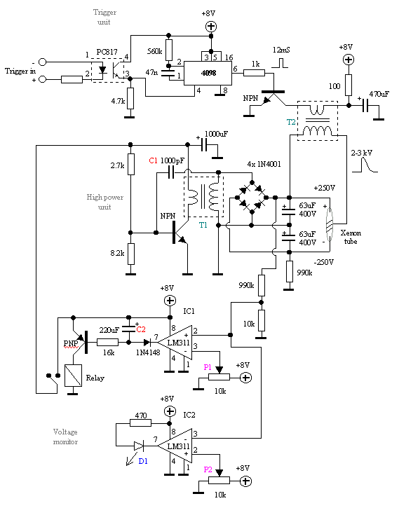
When power is switched on, the power over the Xenon tube is zero. The voltage comparator LM311 (IC1) monitor the X-tube voltage and control a relay for the "high power unit". As long as the X-tube voltage is lover than 230V the LM311 will charge C2 and the relay will pull the contacts together so the "high power unit" get power.
The high power unit is an oscillator. T1 is a 220V to 12 V transformer turned into opposite direction. It upptransform the voltage and a diod bridge (or some diods) rectify the voltage to a DC wich charge the 400V capacitors over the X-tube.
When the voltage reach 230 V the output from LM311 (IC1) will go high. With P1 you can set this level.
C2 will now start to discharge for 16 sec more, the relay will still hold the contacts together. After that 16 seconds, the relay will open the contacts. The power supply to the "high power unit" will be disconected from + 8 Volt. The X-tube voltage is now about 520V and will start to discharge slow. When the voltage drops under 230V the LM311 (IC1) will start the procedure again.
The reason of this is to save battery power. I don't want to charge the X-tube capacitor to more than 520V. If I let the "high power unit" keep running I will go above 520V and lot of current will be consumed for no good.
The other LM311 (IC2) will light D1 when the voltage over the X-tube has reached 420V. With P2 you can set this level.
The "trigger unit" consist of a monostabil vippa CMOS 4098. When it is trigged it will deliver a 12mS puls into T2. T2 is a normal 220V to 6V transformer turned into opposite direction. The output from this unit will be about 2-3 kV. This puls will trigger the Xenon tube and it will flash.
Building
Start to build the "high power unit" and test it. If it won't oscillate try to flip the conection on the transformer. You can also play with the value of C1 (200pF to 10nF). It will vary the charging voltage and the charging-time. When you get that working, conect the bank-capacitor. Remember one capacitor will be charged to +250V and the other to - 250V, totally 500V. BE CAREFUL!!
The "trigger unit" shoulden't be any problem to build, If you have high power over the X-tube an you got a trigger-puls from T2 and still can get the X-tube to flash, you should try to flip the connection on transformator T2.
Performance
It will take about 20 second for my unit to charge. My unit use battery, but if you have other powersupply you can speed up the charging time without any problem.
Copyright © Last modified on 11th July 2001.
 Xenon Flash Indicator (XFI)