50MHz Receiver for the IR Detector
This project is about the receiver for my IR controlled transmitter.
The receiver works at 50MHz and is crystal controlled and will
receive and decode DTMF signals.
All contribution to this page are most welcome!

Background
This receiver belongs to my IR-transmitter project.
To understand this receiver, I advice you first to read about the IR-transmitter.
This project will describe the receiver part I have made for the IR-transmitter. It is a 50MHz receiver based on the MC3371/MC3372 circuit. The circuit is a crystal controlled FM receiver. I have also implemented a dual gate preamplifier to gain sensistivity. This unit will receive and decode the DTMF codes from the transmitter. I have a DTMF decoder circuit MT8870 which will decode the incomming tones and finally a PIC16F84 is connected to the MT8870 to control the system and give sound alarms.
I will fresh up your memory about the 3 DTMF codes I use in the transmitter.
  • Code 19 : It has been a IR-detection.
  • Code 18 : "keep in touch" (sends every 10 second).
  • Code 17 : "beep" (Remote mode).
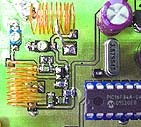
  • Click the pic to see a larger photo with the preamplifier shielded. Click the pic to see a larger photo with the preamplifier un-shielded.
    more pics
    This receiver is small and portable. The power supply is a simple 9V battery.
    One problem with all receiver and transmitter is the antenna. Antenna size and performance is often opposite factors. An antenna (dipol) is quit large specially at 50MHz, but the performance will be much better than a short whip or helical antenna. This portable receiver use 75 cm wire as an antenna. It will give reasonable good reception and will not be too large in size, if you are nothappy with that, you could use a 9-element Yagi antenna if you want...*smiling*

    Block diagram
    Block diagram for the receiver

    Most of this project has been explained in my other projects. The antenna is connected to a preamplifier based on a dual gate mosfet. The preamplifier will also match the antenna and the FM receiver circuit for best performance for the acutal frequency (about 50MHz). The FM-receiver will demodulate the incomming signal to a LF (audio) signal of 100mV. A DTMF circuit listen constantly to the LF signal and when a DTMF tone is present, the circuit will identify it and decode it to a digital number. A PIC processor will read the digital number and make action of the incomming code. The PIC will also make the beeping sound to alarm the user and also control the power to the unit.

    The advantage to use a DTMF circuit is because it is specially designed to decode the DTMF tone from the LF signal. The input LF-signal to the DTMF circuit can vary from 27.5mV to 869mV RMS which is quit good span.

    The filter in the DTMF circuit:
    The low and high group tones are separated by applying the dual-tone signal to the inputs of two 6th order switched capacitor bandpass filters with bandwidths that correspond to the bands enclosing the low and high group tones. The filter also incorporates notches at 350 and 440 Hz, providing excellent dial tone rejection. Each filter output is followed by a single-order switched capacitor section that smooths the signals prior to limiting. Signal limiting is performed by highgain comparators provided with hysteresis to prevent detection of unwanted low-level signals and noise.
    Conclusion: The DTMF circuit is outstanding to recover the data from a bad signal.

    Schematic
    Click on the pic to see a larger photo!

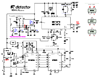
    Click on the pic to see a larger photo! Lets have a look at the schematic. Most of the component I use are surface mounted, that is why you can't see all of them on the photo. The antenna is connected to coil L1 at a tap point (se fig at right). This is to match the impedance. With good match the input filter L1 and C1 will be narrow and reject all unwanted frequency. The input is connected to gate 1 at the dual gate mosfet BF990A. You can use any dual gate fet as long as it has good gain. BF991 or BF981 will work good as well. Gate 2 is connected to half voltage to set the gain. At the drain of the fet, you will find L2 and C2 which is a tuned filter, and this filter also has the same function as the input filter. It will also impedance match the input to the radio circuit. L1 and L2 are not difficult to make. Just make 10 turns around a drill with 7.2mm diameter,and tap it at 2/3 from the cold side. My test has show that this will give good performance. You can of course experiment yourself with different tap points and check which will give the best performance. If you tap L1 closer to the cold side you will make it more narrow, and that can make it difficult to tune. see my Front end design of antenna page to understand why. When the preamplifier is finished you should shield it in some way or else it might not work good. I have build a box of Cu and drilled 2 hole where I can put a ceramic screw driver to tune C1 and C2. Without shielding the preamplifier will detune and be sensitive for hand effects.

    Receiver part:
    The FM-receiver is a basic MC3371/3372 circuit. It has everything you need to build a receiver. A crystal is oscillating at pin 1 & 2 and there is a coil (0.47uH) to make sure it oscillate at third overtone. Before the mixed signal is demodulated, it passes a 455kHz ceramic filter . I have found mine in an old cordless phone. Finally there is a quad coil which demodulate the IF and brings out the LF (DTMF tones) at pin 9.
    Pin 13 is the RSSI output (Relative Signal Strength Indicator) which give you voltage of how strong the RF signal is. I have connected a LED-voltmeter to this output when I tune the receiver. You can read more about this in the tuning section.

    DTMF part:


    This circuit doesn't need much components to work. It need an input frequency of 3.579545MHz, and It need a resistor R1 and C3 to set the time constant to detect a valid input DTMF tone. I will explain how it works. The pin 15 is called Delayed steering output (StD). If the DTMF-circuit detects a DTMF input tone, it will start to charge C3 through R1. When the level has reached a predefined level the StD output will go high indicating that there is a valid input DTMF tone, which can be read by the PIC. If the input DTMF tone no longer exist, C3 will discharge and the StD will go low again. By choosing the values of R1 and C3, you can define how long the input DTMF signal has to be, before the circuit accept it. In my transmitter I send the first key during 50mS and then i have a pause of 50mS and finally the last key for also 50mS. By choosing R1 to 300k and C3 to 100nF, the DTMF circuit want the signal to be at least 30 mS befor it accept it and set the StD high. You can read more detalied info about this in the datasheets. If the StD-time is set to short, the circuit might trigg StD on noise and if you set it too long (longer than 50mS) the circuit will never trigg.

    You may find this receiver too complex with PIC-cpu and DTMF and all.
    I have added this extra to this receiver just to make it possible to send several commands to the receiver and to obtain a reliable communication. I use only two digit in my transfere, but you can use as many as you want. (Example if you use 8 tones you will have 100 milion combinations) such transfer would take 800ms.
    By using DTMF, the radio system will not be so sensitive to noise. With this concept you can use the same frequency for several receivers, you only need to have different ID-number for each receiver.

    Power supply
    When the ON/OFF button is pressed the power will flow through the diod (1N4148) and into the 7805 regulator which will provide the PIC with power. As soon as the PIC wakes it will set RB6 high which will make the NPN and the PNP transistor saturate and the power will continue to flow. The input RA1 probe the status of the ON/OFF button and if this button is pressed again, the PIC will beep and let RB6 go low, which will cut the power to the unit.
    I can now use one button to switch ON/OFF the receiver.

    Tuning
    This receiver need some tuning to work well.
    The preamplifier has a tuned LC circuits. L1 and C1 tunes the antenna (wire about 75cm) to receiving frequency. L2 and C2 should also be tune to receiving frequency and to give best receiving signal and less noise. The easiest way is to shield the preamplifier and drill 2 holes so you can tune the two capacitor. It is important to have good shileding, else it will detune and not work properly. I have build a portable audio amplifier and I use it to tune the preamplifier by conecting the output from the receiver pin9 to the audio amplifier. I can now hear the DTMF signal and it then I walk away some hundred meter from the transmitter and tune the preamplifier until I get the best performance.

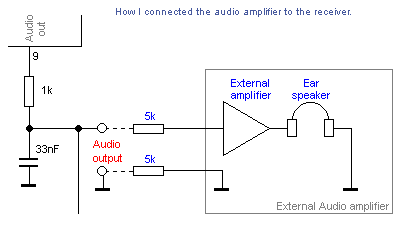
    How to connect an external audio amplifier to the receiver to listen to the DTMF tones. One important thing to remeber is that if you connect a wire to the receiver, for example to the audioamplifier I explained above, you will change the groundplane size and you will tune the unit with the new groundplane. When you have tuned the unit and you disconect the wire, the groundplane change again and the unit will be detuned. What you should do in this case is to connect a 5k serie resistor in the ground wire and a 5k serie resistor in the signal wire, befor it is attached to the receiver unit (See fig at right). The total impedance will be 10k and the ground plane of the receiver will not be affected of the audio amplifier I have connected to hear the signal.
    When I did my test I soldered the two 5k resistor direct on the PCB of my receiver.
    You should also tune the quad coild for best audio receiving!


    Download PIC16F84 program (INHX8M format)
    ir_rec.zip Receiver program, the file is zipped!)

    Download some datasheets
    MT8870.pdf Datasheets for MT8870.pdf

    I hope you will enjoy this 007-project.
    I also hope I have given you some new ideas and knowledge.
    You can always mail me if there is anything unclear.

    I wish you good luck with your projects and thanks for visit my page.


    Back to main Page  |  Contact Me  |  Cheap components

    Copyright © Last modified on 6 July 2002.