50MHz Power Amplifier
This page investigates a simple PA for 50MHz.
This power amplifier will boost upp a low level signal about10-20mW
to over 100mW. The power consumption will yet be quit low.
At the bottom of this page I will present a complete transmitter based
on a crystal controlled VCO.
All contribution to this page are most welcome


Background
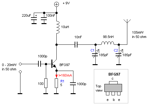
This PA is based on a common cheap power transistorBFG97. I use this transistor in my previous transmitter projects. This PA work in class C and will deliver about 100mW. The current consumption is about 100-150mA at 9V. Why I have choosen 9V as power supply is because I will in most cases use my transmitter with a common 9V battery. If you use higher voltage you will increase the output power. I don't want to consume all to much energy from the battery, so I have settled with 100mW output power. The construction is very easy. The input power to my PA comes from a 50MHz transmitter I have built in previous projects. The transmitter I used delivered about 10-20mW into 50 ohm.
At the bottom of this page I will present a complete shematic for a transmitter that will deliver about 100mW. I guess you will recognize the transmitter hart from my previous projects, I just love this crystal controlled VCO.
Good luck!

The schematic


Now, let's take a look at this schematic. This PA works in class C. Class C amplifiers operates for less than the half input cycle . It's efficiency is about 75% because the active device is biased beyond cutoff. It is commonly used in RF circuits where a resonant circuit must be placed at the output in order to keep the sine wave going during the non-conducting portion on fthe input cycle.
The input power to this device should be around 10-20mW or (+10 to +13dBm). There will be a DC current going through the emitter. Resistor R1 set the power gain and the DC current. A to low resistor value will make the current to high and you will burn your transistor. I found that 5-10 ohm is a suitable value.

The output consist of a 3-pole filter designed to 50 ohm match. C1, C2 and L2 has given the exact values. I would recomend you to replace C1 and C2 with a variable capacitor (or add a capacitor parallel to a regular capacitor) then you can fine tune the output for best performance. A 150pF capacitor parallel with a 80 pF variable capacitor will do good. The antenna should be 50ohm type, wich means a 1/4 wave lenght whip antenna will be perfect.

I have choosen the voltage to 9V because I use a battery and this little PA will give you more than 100mW output power. The current consumption is about 150-200mA. The transistor didn't get hot at all. You could increase the power and you must then increase R1 as well (keep the current around 150mA) and you will get even more power from this PA.


The 100mW transmitter


I have explained this transmitter before, but I will make a brief summary. Coil L1 is to tune the transmitter to desired frequency. It is for finetuning the transmitter. Crystals do have a little error in frequency. You can change the frequency by some 10:th of kiloherts. C1 and L2 is a resonans circuit and should be in resonans at 50MHz. L3 and the 10pF and the 6.8 pF capacitors is also tuned to 50MHz. This filter cleans up the signal before it goes to the FET BF245B.
The FET is working as a follower, it doesn't amplify, it just boost up the current. I have made a slightly changes by replacing the source resistor with a coil. I noticed that I could get more power out of this FET with a coil than a 1k resistor. You can play a bit yourself to find the best output power. Next stage is a booster. The reisistor R2 set the current and the gain of this booster. A to low value will increase the current and you might end up blowing the transistor. I usually use 20-100ohm. A dissadvantage is that the current consumption will increase and if you are using battery it will be empty faster. The current consumption in the emitter is not proportion the output power.

Connect a 50ohm resisitor in serie with a 10nF capacitor and connect the capacitor to the colector and the resistor to ground. Don't connect the last stage yet. Now you can measure the output power over the 50 ohm resistor. I use an oscilloscope and then I play with the value of R2 and I also tune C1 and L3 for best output power. In my measurement I come up to about 17mW into 50 ohm with 9V DC in this exactly construction.

Now it is time to connect the last stage. You can also play with R3 to set the desired output power. Be carfull because it is very easy to blow the transistor. You can go down to 2 ohm , but the current will be high and the transistor is not made for so high current and it will probably get hot. If you use 5 ohm the transistor will not be hot and the total current consumption will be about 250mA and you well get over 100mW of output power. The last thing you will have to tune is the antenna filter.

Tune the antenna filter for best SWR. I don't have such unit but all transmitters are most often built to work with a reciver. I have a receiver with a RSSI indicator(strength meter). What I do is to put the receiver a bit away from the transmitter and I connect the RSSI-voltage to a large display so I can be several meters away from the receiver and still be able to see the RRSI-voltage level. Then i sit there and tune the transmitter till I get the best strengt. Now I really know that my transmitter is tuned for best performance, specillay with that receiver.
This is the receiver I use to this transmitter.

Good luck!


Back to main Page  |  Contact Me  |  Cheap components

Copyright © Last modified on 29th Jan 2002.