50 MHz Receiver based on MC3372
The purpose of this project is to build a simple receiver for 50MHz.
The Receiver is built around the circuit MC3372, wich is a narrow band FM receiver.
The receiving frequency can be set with a LC tank or with a crystal.
To increase the sensitivity of this circuit I have added a antenna preamplifier.
All contribution to this page are most welcome!
Background
I need a simple solution for receiving narrow band FM signals. I have found a circuit MC3371/MC3372 wich is very simple circuit to handle.
I wanted to build a receiver wich can handle all kinds of signals. I both want to receive audio and data.
To increase the sensitivity, I have added a dual gate input FET amplifier.
The complete receivier will be built into a metal-case and used with a external audio amplifier or microcontroller.
One purpose of this project is to build a unit wich can be used to several different object. Example: Garage door opening system,
controlling lamps, alarms, bugging devices, portable phones, give a reciver to your local pizza delivery and you can buzz them any time for home delivery.
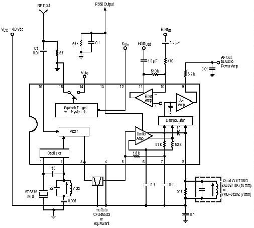
The pic below shows the interna block in the circuit
As you can see the circuit contains everything one need for a receiver.
The 455kHz ceramic filter is a narrow band filter. You can find 455kHz keramic filter in AM section in some old radio.
However the best filter is a sharper type found most often in old cordless phones, maybe there is some place to order them.
The audio demodulator is a LC unit (quad coil) tuned to 455kHz. This type of quad-coils is often found in AM radios. It is a CAN
with yellow slug. The MC3372 can be used with a ceramic resonator instead of quad coil.
Inside the circuit is a operational amplifier wich can be used to amplify the audio signal and there is a squelch unit.
The circuit need just a few componets to work, and the sensitivity is under 1 uV.
I have still added a preamplifier to improve the selectivity and the input stage. If you want you can exclude the preamplifier, but
the reciving will not be as good.
Some measurement on the internal amplifier
Inside the MC3371/MC3372 is a OP-amplifier. I tested the circuit with +8V DC. The schematic above show my results. The DC level
at pin11 is 5.8V. I applied a signal about 1-2mVand the signal was amplified at pin 11 to 1.1V. When the amplitude was about 1.2V the
signal was distored because the top level had saturated. The conclusion is that the max AC output level from the OP without distortion is 1.2V.
I applied a square-wave signal to the input and measured the output. The signal jumped between 3.4V (low) and 7.8V (high).
I tested with different input voltage from 4mV to 150mV and the output had the same level.
Some measurement on the internal squelch-trigger
I connected a resistor (1k) from the Mute (pin14) to Vcc. When the Sqin reached 1.04V the mute (open colector) went high and when the
Sqin-voltage decreased below 960mV the mute went low again. The hysteresis is about 50-60mV. I will not use the squelch in this project!
The complete schematic of the 50MHz Receiver
Preamplifier:
The preamplifier consist of a dual gate mosfet. I have fall inlove with the type BF990 and BF 991. They are surface mounted and
have good performances. You can use many different types, just check that they have low noise value and high gaing.
There are two hand made coils in this construction, L1 and L2. I used a drill with 7.2 mm diameter and I made them 10 turns.
It will give you about 650 nH. Coil L1 is taped at 5 turns. This is to impedance match the preamplifier with the MC3372 circuit.
How do I know the tap should be at 5 turns, well I have been testing my receiver with different tap points and I have found that
a tap at 5 turns will give you the best performance. You can play yourself with different taps and test your receiver.
The antenna should also be connected to a tap point close to the cold side of the coil to give the best performance, see my
Front end design of antenna page to understand why.
Well, I have also made some field test and I have found that the best performance will be if the antenna (80cm wire) is connected to
the top of the coil. The selectivity will not be so good, but the overal performance will till be best this way.
If you want you can play with this tap also. I made one receiver with the antenna connected to tap point at 5 turn and
the receiver worked well. To find the best performance you should attach a voltmeter to the RSSI output and
tune the preamplifier for best readings. Easiest is if you use an analogue instrument.
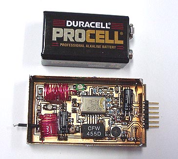
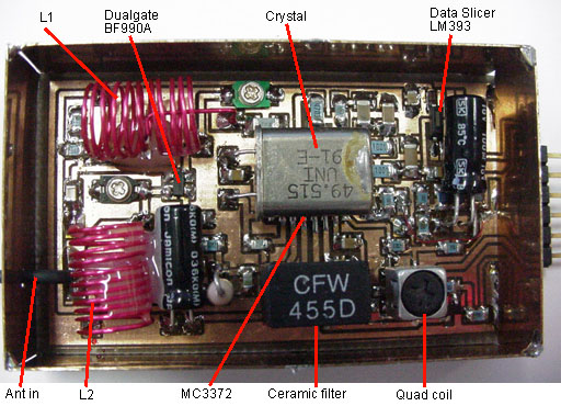
Photo of my Receiver:
Local oscillator:
The circuit contains a oscillator, you just have to connect the crystall and some few compontents. You can measure the
frequency at pin 1, 2, but use a high impedance probe.
Data Slicer:
The analog output is feed to a schmitt-trigger with 0.8 V hysteres. It means that the output signal must be higher than 0.4V and lower
than -0.4V to change state. By this way you will get a data signal cleaned up from noise.
As you can see in the schematic, a voltage divider bias the minus-input of the comparator. The DC level at this input is 4.5V.
Added to this DC is the analog signal applied via a 100nF capacitor. The toggling level at the output of the coparator will therfor
be: 4.5V +/- 0.4 V : So, 4.9V will make the output go low and 4.1V will make the output go high. As you can see the output is
inverted to the input signal.
The hysteres is determined by the resistor between pin 1 and pin 3 (100k) and the resistor to pin 3 (10k).
The hysteres will be: 4.5 V * ration in my case (10/10+110) = +/- 0.41 V.
If you want to play with the sensitivity of the dataslicer you can replace the 100k resistor with a 500k pot.
Audio output:
The internal op in the MC3372 is capable to drive a small speaker/headphone. You might have to increase the amplification a bit by
increasing the 500k resistor at pin11.