Introduction to microcontroller PIC16F870 and PIC16F84
Give this page one evening and you will always carry a great knowledge,
and have a very powerfull tool in your workshop.
The purpose of this project is to understand how a microcontroller works
and how you can make your own small programs.
I will explain the circuit and make a simple software example for you to follow.
At this page, you will find all software/hardware you need to learn and use
the PIC16f870 and PIC16F84.
All contribution to this page are most welcome!

Background
Don't be afraid and think this is too complicated for you, it is not. The common idea is that a microcontrollers are very complicated to use and need thousand of houres to learn. Yes, that can be true if you are going to make a voice recognizion program using fast fourie transform *smiling*
Most often the microcontroller handles much easier tasks. I use the microcontroller in many of my radio-project since there are many circuit that have a digital interface which need some kind of programming (example a DDS circuit or a PLL circuit). I some of my project I use a microcontroller to handle the communication to/from a computer.
I will first explain what a microcontroller is and we will take a look inside two commonly use microcontrolles (PIC16F84 and PIC16F870). The purpose of using these two is because they are so easy to learn and you can re-program them thousand times.
I will try to explain in a simple way and I can esure that you will understand all when you follow my programming examples below.
You need a real eaxmple to really understand the microcontroller.


Block diagram
Lets have a look at a simplyfied blockdiagram of the interior of the microcontroller. In the PIC16F84 and PIC16F870 you will find and work lot with this four blocks.
  • The program memory (green) contains the program you have written. The program is a set of instruction that the microcontroller will perform for you. The software (instructions) will be written in a computer and then programed (burned) into the "program memory". This memory is a EEPROM memory which can be rewritten thousands times. I will later explain how you can build a programmer to your computer for programing this area.

  • The REGISTER and RAM box (orange) contains all the internal registers and a small RAM memory where you can store data temporary. There are several register with different functions. (I will explain some of them in the example later) The RAM memory is not large about 64-128 byte. Example: If you make a program loop, then you need a variable to change value each time the loop runs and then you will use a variable defined in the RAM adress to hold the counter value.(I will explain more later, don't dig yourself into the now) The content in the Register and RAM-info will dissapear when the power is off.

  • There is another memory wich will work the same as the RAM and that is the EEPROM-memory (yellow). This is a small memory where you can read and write data aswell, but the data will not dissapear when the power is off. Next time the power is on you can go into this memory and fetch the data again. Example: If you make a code lock alarm, where you have to push 4 button to deactivate the alarm. You can stor the right code in the EEPROM and just compare the actual pressed keys with the value in the EEPROM. You can then easy change alarm code by rewriting the key in the EEPROM.

  • The last box (blue) is the port of this circuit. The port is the input and output pins of the actual circuit. You can define the pins as input or outputs. By writing or reading to the port you can control each pin as you wish. In my program example you will understand more.

    The PIC16F870 is a later version of the PIC16F84 and both circuits contains much more blocks than the four I have described. I advice you to read the datasheets of the two circuit to get all details of every block. I don't want to confuse you with lot of extra info right now, but remeber you don't need to use all other block if you don't want to! Both controllers has timers, watchdogs, interupts, counter and lot of other blocks.

    Actual circuit- HARDWARE of PIC16F870
    I will now focus on the PIC16F870, since it has most good stuff inside, most ports and is the cheapest one.
    The picture below show you the hardware pin of the circuit.( Be calm, I will guide you..*smiling*)


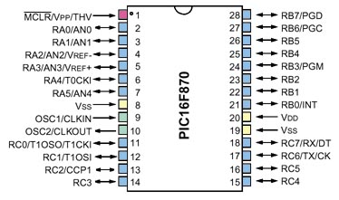
    Lets focus on the color i have put on the pin and not on the text at each pin.
  • The blue pins are ports (input/output). Since there is many extra function in this micro controller, some pins can be used for several purpose. Some pins can be used as inputs to an internal AD and some pins can be conected to an internal counter etc.
    First we will learn to use the blue pins as simple inputs and outputs.
  • The two green pins should be connected to a crystall to obtain an internal clock signal.
  • The yellow ones are for power supply.
  • The red one is the reset input wich will reset the circuit.

    So far it shouldn't be to complicated to understand.

    Internal Registers
    There are several internal register in the microcontroller. Each register has an adress. In the datasheets at page 12 you will find all of them. Remember you don't need to know all of them to be able to use the microcontroller, but there are a few wich you should understand.
    For example at adress 3 you will find a register called STATUS. You can find this register at page 16. Lets take a closer look. You don't have to understand the purpose of each bit now.
    This register is 8 bit wide and each bit will give you some information.
    Bit 0 is the CARRY.
    Bit 1 also kind of CARRY
    Bit 2 tells if an arithmetic or logic operation is zero
    Bit 3 Go high after a power up
    Bit 4 Indicate a Time out from and internal block
    Bit 5 and 6Select bank (see text below)
    Bit 7Select bank (see text below)

    The register are divided into four section (Bank 0 to Bank 3). Before you access a register you must set the bank you which to access. Bit 5,6,7 will set actual bank. As you can see the STATUS register can be accesed from all four banks. The software example will explain it for you.
    I advice you to read the datasheets to get the full picture of the bank and all the register functions. It can feel hard and boring, but don't dig yourself into details right now.

    An example is the best way to learn
    The PIC16F870 has 35 instructions. In my example below I will use some of them. I advice you to read about the instruction in the datasheets at page 106.
    One register you will work lot with is the W- register. It is an internal register which is used in many instructions.

    Below you can find two example. The first example will make an output pin go high, You can connect a LED to this pin to verify the signal. Next example will make the pin (LED) blink.
    The .asm file is the code I have written. When the computer assemble (transform your code to instruction for the microcontroller) the program it checks that there are no error in the code and then transform the code into hex file, which is pure data that we will burn into the microcontroller. After assembling, you will also get a file called .lst.
    This file is contains both the code you have written and the digital operation command (hex cod) for the microcontroller.
    The .lst file is pure information for you. If you have made any error you will get a message from the assembler program and you can see at which line the error occured and you can go into the .lst file and check what was wrong. The .asm will never be changed by the compiler.

    Please follow the .asm file and read the comments I have made for each line and you will understand how the microcontroller works and you will aslo learn a few instructions.

    This example will make an output pin go high.


    This exampe will make the same output toggle (blink).


    PIC assembler explanation and samples
    Here you can download a very good documentation about assembler with samples and explanations.


    Great EBOOK about PIC16F84
    Here you can find a very good documentation how to learn all about PIC16F84. It is worth a visit and it is free.

    Download assembler
    There are many assemblers for the PIC16F84 and 16F870. My advice to you is to visit microchip:s homepage and dowload the software there. Here is a direct link to their assembler. latest version of MPLAB The software is free and you can mail them if you want to have a free CD with all software and datasheets. Microchip has made a complete software enviroment where you can simulate your software befor you program the circuit. This enviroment is called MPLAB. Development software (MPLAB® IDE)

    Download Programmer
    When you have assembled the code you will have a .hex file which now needs to be programmed into the microcontroller. To do this you need a little interface (programmer) from your computer to the microcontroller and you need a software program which handle the programming.
    Here is a very nice software to program the PIC. You can use this software with many programmer and you can program many circuit in the PIC familly. Go to this link at bottom and down load IC-Prog Universal programmer
    install the program and the first time you run the program it tells you to setup "hardware settings". The IC-Prog is written so you can use many programmers. If you use the schematic I have made you should set the settings like this:

  • Schematic of the my hardware programmer.
  • My Hardware settings

    Configuration :
    When you run IC-Prog and choose PIC16F870 circuit, you will have to set some configurations (at the right of the screen).
    Below I will explain all the configuration settings.

    Oscillator:
    The oscillator of the circuit can be run with four different types. I always use XT which stand four Crystall ocillator. (At page 119 in the datasheets you can read about the four different oscillator modes)
    Code protect:
    If you don't want anyone to be able to read the content in your circuit you can protect it.
    Fuses:
  • Watchdogtimer (page 101 datasheets)
  • Poweruptimer (page 89 datasheets)
  • Brow out reset enable (page 94 datasheets)
  • Low Voltage Programming Enable
  • Code Protection Data Enable
  • Flash Program Memory Write Enable
  • Brow out reset enable (page 103 datasheets)
    In my example above I have disable all the fuses.

    Microchips homepage
    microchip
    datasheets PIC16F870
    Programming specification of the PIC16F87X

    Final word
    I have given you a quick tour in the microcontroller world. Now it is time for you to explore by yourself. You have all the tool needed to make program and you can now build your own programmer for the microcontroller. Do read the datasheets, they use simple language and explain in great details.
    You can always mail me if there is anything unclear.

    I wish you good luck with your projects and thanks for visit my page.


    Back to main Page  |  Contact Me  |  Cheap components

    Copyright © Last modified on 12th aug 2002.