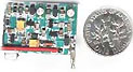
50 MHz crystal controlled bugg
This bugg is based on my previous 3-transistor transmitter.
This bugg unit has many advantage.
The transmitter use a crystal 46.515MHz to hold a steady frequency.
The frequency can be fine-tuned by some 100kHz.
The transmitter can send data and audio-signal with +/- 10kHz FM modulation.
The output power is about 10mW into 50 ohm.
All contribution to this page are most welcome!
The material presented on this page is for educational purposes only. The author does not practice or endorse the monitoring of telephone conversations in any manner, as it violates Federal law. What this page provides is information - how it is utilized by the reader after they leave this website is their responsibility.
Background
There are so many buggs out there on the internet, but few of them works good. Most of them are build
around one transistor. This transistor works as an oscillator at 88-110MHz. To FM the RF signal this transmitter use the internal stray capacitans
in the transistor to change the transmitting frequency and thereby achieve FM (frequency-modulation) with the signal from a microphone.
The disadvantages of this type of transmitter are:
The transmitting frequency is not stable.
The output power is low.
You don't know the exact transmitting frequency.
Any one with a radio can pick up your signal.
How many time have I not seen homepages that tells you to buy buggs smalls as a coin (look at the pic at right). What thay didn't tell you
is that you also need an antenna and you need a battery Those part will sertanly not be small as coins.
So I have developed a bugg myself!
I wanted a easy build bug that is crystall controlled. Finally I come up with this piece.
This bug use a capacitor-microphone and use 2 transistors to boost up the signal. The MIC has 5-10mV output signal
and I amplify this signal to 500mV, about 50 to 100 times.
I guess you will find that the RF part of this transmitter is almost the same as my previous transmitters.
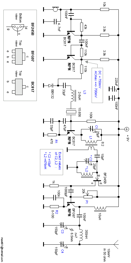
This transmitter oscillate at the fundamental frequency (15.6566MHz) and a frequency trippler has been added.
Finally a power amplifier boost up the signal to the output.
The transmitting frequency can bee changed quit lot (100kHz), so the unit can be matched really good to the receiver. The
frequency can also be changed by applying a DC voltage to the varicap (BB132). The frequency deviation can be +/- 10kHz.
I have measured the output power to 10mW into 50 ohm.
The transmitter will work fine from 40 to 50 MHz, so if you don't have the 15.6566MHz crystall (wich you most probably don't have) you
can use others.
The crystal I used is a 3:th overtone crystal. The coil L1 is a slug tuned coil. The primary winding is 8 turns and the second winding is 2 turn. The inductance in the primary winding is about 800nH.
L1 and C1 should be in resonance at 47MHz. The number of turns is dependent on type of coil you have. You will have best performance
when the "ferrite tuning slug" is at the bottom of the CAN, because you will then have the best couppling between the two
windings. Do like this: Wind primary and secondary winding on the core and turn the slug to the bottom of the CAN. If you can, measure
the inductance in the primary winding. It should be around 800nH. Attach a oscilloscope to the colector of the NPN transistor or to the second winding.
You should see an oscillation. Tune C1 until you find the 3:d overtone. You won't get a perfect signal at 47MHz. You will probably
find a very jumpy signal because of other harmonic frequencies. Don't mind that, just try to tune until you find some proper signal,
anyhow you will know that the oscillator works.
L2 and C2 help to clear up the 47MHz signal. L2 should be 300-700nH also a tunable coil. C1 and C2 should be in resonans at 47MHz.
I measured L2 and C2 in my construction and come upp with L2=476nH and C2=10pF.
The FET transistor is a voltage follower with very high imput impedance and low output impedance. You can attach an oscilloscope
at the source of BF245B. You should find a much better 47MHz signal here. Now, tune L2 and C2 until you reach a nice shaped signal with
max amplitude. Tune also L1 and C1 for best performance.
The last stage is a power amplifier. This unit doesn't need any tuning. I guess you can use many different type of transistors here.
I have used the BFG97 and it gives quit good power. I haven't been experimenting much with other types. With P1 you can set the current in the
transistor. You will have to experimient to find a suitable working current. I replaced this pot with a resistor of 7.5k.
You can also experimtent with resistor R2. The lower value the higher current consumption and the more output power.
The finetuning of the transmitting frequency is made with L3. This is also a tunable coil.
The inductance of this coil can be changed from
2-8uH. The exact value of L3 at 50MHz was 6.8uH in my experiment. You will have to play a bit to find the best inductance range for you transmitter. Just connect a frequency counter to the output
and tune L1 to the desired frequency. You can easy change the frequency some 100kHz. To match the receiver you should start the receiver and then tune the transmitter until you reach
the best signal from the receiver, then you will know that the two units are in perfect match.
Tune C3, C4 for best output power.
The two NPN transistors (BC817) works as amplifiers. They amplify the audio from the mic. The voltage to the varicap is
about 750mV DC and the audio-signal is about 500mV AC.
PI network C3, C4
A PI filter match the antenna load.
Both capacitor C1, C2 should be tunable. Tune the two capacitor for best performance.
The output power is easy 10mW. Remember that high transmitting power also consume battery!
Tuning
The best way to tune a transmitter for max output power is to measure the RSSI from the receiver.
Do like this:
Connnect a voltmeter to the RSSI output from the receiver. Put the receiver a far away as possible from the transmitter, but
you must still be able to sea the readings from the voltmeter. Now, tune the transmitter until you reach the highest readings
from the receiver. Now you know you have tuned the transmitter for max output power and frequency match.
will aand A PI filter match the antenna load.
 50 MHz crystal controlled bugg
 All contribution to this page are most welcome!