IDE Hard Disk experiments.
This project will explain how an IDE disk drive works.
You will also learn how to control it and how to read and save data to your disk.
Build your own interface and get advantage of the mass storage of data in a hard disk.

You will be amazed how simple it is to control and use the IDE disk.
All contribution to this page are most welcome!

Background
The main reason for me to learn about IDE disk is that I want to be able to save large quantity of data.
What can store much data info with high speed?

Well, there is RAM memory, recording circuits, memory sticks, but the superior storage unit is
a hard disk commonly used in computer. You can find an old disk really cheap.

The great thing with IDE hard disk is that all difficult controlling electronic is integrated in the disk unit and you don't have to worry about it. All you need to learn is the interfacing, which is simple. I will show you!

Below I show you the two controller units I have made to learn and play with an IDE hard disk.


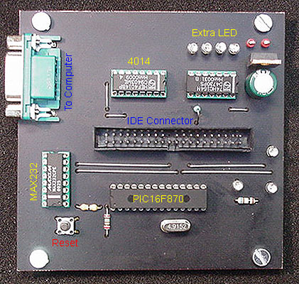
This is the controller card I have made.
It receive info via RS232 and then control the IDE disk via standard 40 pin connector to the hard disk. This card is not made to be a fast interface, it is made for you to learn how an IDE hard disk works and how it can be controlled to read and save data.

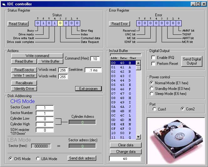
This is the windows software I have made to control and test the IDE hard disk. With this software you can set registers, read registers and make all the test you need to learn how an IDE hard disk works.
Don't worry, I will explain exactly how it all works.

Basic understanding
The left figure below shows the internal registers in a IDE hard disk.
The IDE hard disk can actually be compared to an ordinary memory circuit where you define
an address (yellow box) and then read or write data to the unit (green box). I will explain more in a second.

The right two figures show the internal mechanism in a IDE hard disk.
Inside the hard disk case is 2 or more disk platter (se right figures above).
There is also two read/write heads (top side and bottom side) flying on each disk platter.
The read/write head is placed on an arm called "head arm" which is connected to an actuator.
The acutator is a magnetically coil which put the arm and heads in desired position on the disk platter.
The read/write head can move from the centre to the outer edge of the disk platter.


So, How does it all work?
There is 5 interesting blocks (register)in the figure above. They can be accessed by 5 address lines CS1, CS0, A2, A1, A0.
  • Addressing (yellow)
  • Databuffer (green)
  • Error (pink)
  • Status (orange)
  • Instruction (lightblue)

  • Let's analyse the addressing part (yellow box) together shall we.
    The addressing off data in a IDE hard disk can be working in two modes :
  • CHS mode = Cylinder-Head-Sector

  • LBA mode = Linear Block Addressing


  • CHS mode
    Sector:
    The data on a IDE hard disk is not addressed in byte by byte. The data is grouped in block of 256 words (called sector).
    Therefore each transfer of data to/from the hard disk will always be 256 words. (one word = 2 bytes = 16 bit)
    The addressing (yellow box) consist of three registers. Cylinder, Head and Sector.
    By setting these registers you define an address to a unique sector for reading or writing a data block of 256 words.
    The sector address register is a 8-bit register, which can point from sector address 0 to sector address 255.
    Head:
    The head address register is a 8-bit register, which can point from head 0 to head 15.
    Remember that the hard disk has 2 or more disk platter and each disk platter has 2 read/write heads.
    Cylinder:
    The cylinder or should I say cylinder-track is two 8-bit registers, which define the read/write head position on the platter disk.
    The value of the two register can go from 0 to 65535.

    I have a Western Digital IDE Hard Drive and the label say it is 6448MB.
    It also say it has 13328 cylinders, 15 head and 63 sectors.
    Let's calculate and check!

    13328*15*63*256 = 3224309760 words = 6448619520 bytes

    Great, it seems to be right!

    LBA mode
    This is another mode you can use to define the addressing. This mode is a bit more simple to use.
    This mode also use the head and cylinder, but also a register called sector number.
    Together these register will define a 32 bit address which point to the data block you wish to read/write.
    Each data block is still 256 words. The picture below show you how the register forms the 32 bit address.


    In LBA mode you don't have to worry about numbers of sectors, cylinder or heads.
    You can simply define the address as a 32 bit number from 0 to total disk size.
    Example: My 6448MB disk will have LBA address from 0 to 12594960 ( 0 to C02F10 hex).

    Data buffer
    We have discussed the addressing and I have already said little about the data buffer. The databus is 16 bit long (1 word), all other register (example Cylinder, Head,...) are 8 bit (byte) and uses the low 8 bit of the databuss.
    The databus is used for reading/writing data to the IDE hard disk and to set the registers I explained above.
    The data on the IDE hard disk is put in packages of 256 words. In practical way it means that you point to an address and then you either read or write 256 words to or from the data buffer of the IDE hard disk. In the lower left corner of the picture above you find addressing signals called CS1, CS0, A2, A1, A0. These address lines are used to point to different registers. There is also a read signal and a write signal, but I have not drawn it.
    I will later give an example how to perform a Read/Write.

    Error Register
    If an error occur during a Read/write cycle or addressing this register will contain information about the error.

    Status Register
    The status register will give you the status for different actions.
    Example, you get info when the disk is ready for action, when data buffer should be filled...error occurred.
    You read all about it in the "Connecting IDE Drives by Tilmann Reh" link below!
    Great Work Tilmann!!!

    Instruction
    Now, the IDE hard disk has several instructions which it can perform.
    So what is an instruction?
    An example of an instruction is "power down the disk" another is "write a sector"..
    In most cases you will only use a handful of them.
    Here are the once I use mostly:

    E0h = Spins down the drive
    E1h = Spins up the drive
    20h = Read 1 sector
    30h = Write 1 sector
    10h = Recalibrate, move the head to cylinder 0

    Example: Let's say you want to spin down the drive!
    You should then set the CS1, CS0, A2-A0 to point at the Instruction register. See "Connecting IDE Drives by Tilmann Reh" for details.
    Then you put E0h to the 8 lower bit of the databus and perform a Write pulse.
    You will hear the IDE disk drive go down in speed and stop.
    To start it again you have to point and the Instruction register and now you put E1h to the 8 lower bit of the databus and perform a Write pulse.
    The IDE disk will spinn up again...simple ha!

    Example: Let's say you want to Read a sector 10h
    Let's say we use LBA mode!
    LBA should be 0000010 hex. I set the CS1, CS0 and A2-A0 to point to Head register and put the register value on the databus (low 8 bit) and perform a writepulse.
    The write puls load the pointed register with the data.
    I then do the same with Cylinder High, Cylinder Low, and Sector Number register. All must be loaded.
    The LBA address is now entered into the IDE hard disk.
    I now perform the instruction called "read 1 sector" by pointing the CS1, CS0 and A2-A0 to the "Instruction register" and put 20h
    to the 8 lower bit of the databus and perform a Write pulse.

    The IDE disk drive loads the buffer internally with 256 word from sector 10h.
    I now set the CS1, CS0 and A2-A0 to point to "databuffer register" and I can now read the 256 word from the data buffer.

    IDE Software
    The software I have made will help you to experiment with your IDE hard disk and you can make lot of fun tests. You can perform any instructions, read status, read error, you can read sector, write sector and you can handle power control.
    Below I will explain the software in details. I really suggest you read the documentation (link below) about the IDE hard disk before you jump into my program.
    It is much more fun to understand what you are doing with the IDE disk drive.

    Install the program and connect the IDE disk drive. One good thing to know about the software is that by hovering with the cursor above buttons and texts you will be able to click and read deeper info. In my software you will find several boxes.
    Up in the left corner you will find "Status Register" and I will start to explain this register. This register will give you information about the status of the IDE disk drive and the last action performed. You can see the 8 bits and if the bit-boxes are blue, nothing has happened since last update. If some bit change the box will be yellow. This is done to make it more simple to see if anything has happened.
    So if you press the "Read status" button the software will send info to the PIC to check the status register in the IDE hard disk.
    For example when the drive has spin up after power the "Drive ready" bit 6 will go high.
    If an error occurs the "Error flag will go high" bit 0.
    You can then go the "Error Register" right box of the program. Here you can press the "Read error" button and get the information about the error.
    Now, lets go to the boxed called "Power Control" Right side.
    You can see it is set to normal Mode. If you click Standby mode the software will send instruction the the PIC so it will make the disk go into Standby Mode and you will hear the disk spin down.
    What the PIC actually do is that it perform the instruction called E0h = Spins down the drive I explained it above in the text.
    Let's look at the "Disk Addressing" box. Left lower side
    At the bottom you see a check box where you can choose to use CHS mode or LBA mode.
    Default is set to CHS mode. You see the LBA is shut down. Only one can be active at a time.
    In the CHS mode you can enter the data corresponding the register you wish to update. I LBA mode it is more simple because you don't have to care to set each register you just have to enter the LBA sector you wish to access.
    When you are ready you push the "Send disk address" button and the software and PIC will update all register in the IDE hard disk.
    Nothing special will happen yet because all you have done is to set the address pointer.
    Let's make some actions!

    At the right side you will find the "Action" register.
    The action register often works with the "In/out Buffer" which will show you the data in the data buffer. It will only show the 8 low bits. I don't care to show the 8-high bits. So let's go through the buttons in the "Action" box then.
    If you press the button called "Recalibrate" the IDE disk drive will perform a calibration and go to sector 0. You will hear lot of sound from the disk...you can hear this sound from the IDE hard disk when you turn on a computer. You will recognise the sound...*smiling*
    Nothing more will happened!
    The button "Read Sector" will perform the IDE disk to read one full sector and you will see the data in the box called "In/out Buffer".
    The button "Write Sector" will perform the IDE disk to write one full sector from the buffer the box called "In/out Buffer". The Seektime box will show you how long time it took for the Read/write head to find the track.

    REMEMBER THIS: You must always send the disk address BEFORE you make a Read sector or Write sector!!

    If you wish to send a single instruction to the IDE hard disk you can enter the command and press the "Write command" button. You see the command is set to 10h as default. 10h is the same as make a calibration. If you would have send the command E0h you would have spin down the drive.
    If you send the command 20h (Read sector) you will see the "Status register" bit 3 (Data request) change to high. This indicates that the buffer is full and you should read it.
    By pressing the button called "Read buffer" you will read the buffer and you will see the content in the "In/out buffer". If you would have send the instruction 30h (Write sector) you will again see the "Status register" bit 3 (Data request) change to high. This indicates that the buffer wants data.
    By pressing the button called "Write buffer" you will write content in the "In/out buffer" into the IDE disk drive.

    The button called "Identify drive" will make the drive send data about itself. I advice you to read about it in the "Connecting IDE Drives by Tilmann Reh" link below!

    Button "Exit program" will shut down the software!

    In the box called "In/out Buffer" you will find two buttons. By pressing "Clear data" the buffer will set all bytes to ffh.
    If you want to change a byte you just point on the byte and then you enter the new value in the box below and press the button called "Change data". In this way you can simple change data in the buffer.

    Now it is time for you to experiment yourself.
    Good luck.

    By reading these documents you will get it all clear
    Connecting IDE Drives by Tilmann Reh
    Wesley's PIC Pages: IDE Controller
    Fil's FAQ-Link-In Corner: IDE Ref.

    Deeper information:
    ATA-1 (IDE) Standard - Revision 4c
    ATA-2 (EIDE or FastATA) Standard - Revision 4c
    ATA-3 Standard - Revision 7b
    ATA/ATAPI-4 Standard - Revision 18
    ATA/ATAPI-5 Standard - Revision 3
    ATA/ATAPI-6 Standard - Revision 3
    ATA/ATAPI-7 Standard - Revision 0 - Vol 3


    Schematic, Building and testing
    The hardware for this project is very simple to build. A few circuits and so. Make sure you use a proper power supply. Use one from a computer. You will then get the wires right and you will have enough power. At startup the driver will consume 1A then it goes down to about 200mA.


    Download PIC16F870 program (INHX8M format)
    ide_3.zip IDE hard disk software (the hex file is zipped!).


    Windows software
    Download windows software
    ide.zip (2.12Mb)
    Click here to go to the software download page!

    Final word
    This project is explaining how you can control an IDE hard disk
    It can feel a bit trick in the beginning, but I really advice you to read the documents I have linked. Together with my software you will learn how it works and soon you will be able to implement an IDE hard disk in your own projects.

    You can always mail me if there is anything unclear.
    I wish you good luck with your projects and thanks for visit my page.


    Back to main Page  |  Contact Me  |  Cheap components

    Copyright © Last modified on 15 feb 2004.