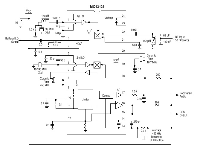
MC13136 Narrow band receiver
The MC13135/MC13136 are the second generation of single chip, dual conversion FM communication receivers developed
by Motorola. Major improvment in signal handling, RSSI and first oscillator operation have been made.
Complete Dual Conversion FM Receiver
Input frequency range 0-200MHz
Voltage byffered RSSI with 70 dbof usable range
Low voltage operation 2-6 VDC
VHF Collpits First LO for Crystal or VCO operation
Isolated Tuning diod
Buffered first LO output to drive cmos PLL sythesizer
Frequencies Measuring
This receiver is built to receive at 79.6625MHz. If you want to receive at other frequency you must get a crystal for that frequency.
You can still follow the text below, but the calculation will different for different crystals.
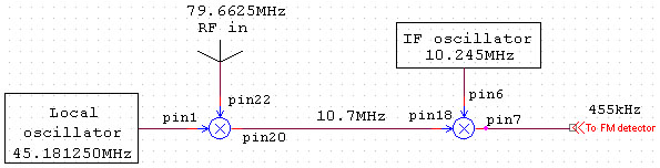
The frequency I want to receive is 79.6625MHz. The crystal I am using is a 3:e overtone witch oscillate at 45.181250MHz.
Attach a frequency counter to pin 3 if you want to measure the frequency. This is the exact half frequency that I want to receive. In the receiver mixer the RF (79.6625MHz)
will mix with the Local oscillator (45.181250MHz) and also with the double frequency of the Local oscillator (90.3625MHz).
The product of the frequencies will be : 2* 45.18125MHz - 79.6625MHz = 10.7MHz (fig below). This signal will appear at pin 20 on the MC13136.
After passing a filter the IF signal enters mixer 2 and mixes with the 10.245MHz Crystal oscillator. The product is a 455kHz signal at pin 7. The 455kHz signal will
pass a narrowband filter and then enter the FM detector.
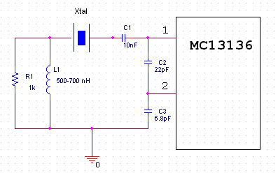
To make the 45.181250MHz crystal oscillate at correct frequency I add a coil and a resistor (Fig below).
The coil will make the crystal to oscillate at its 3:e overton. You might have to adjust the value of the coil to set the frequency right.
I noticed that the ocillator will vary about 600Hz if the coil value changes from 550nH to 650nH.
To be sure that your Local oscillator works, attach a frequency-counter or a oscilloscop to pin 3 at MC13136 and adjust the coil. In my example I measured 44.181345MHz.
You can also controll the 10.245MHz oscillator at pin 6.
I have tested 2 crystals, some of the measurements :
45.181250MHz Crystal :
Coil Value 650nH gives 45.181245MHz ==> the oscillator is +190Hz
Coil Value 450nH gives 45.181657MHz ==> the oscillator is +814Hz
The IF oscillator is 10.243795MHz ==> -1205Hz
For 650nH the total frequency error is +190 - (-1205) = 455kHz +1395Hz
For 450nH the total frequency error is +814 - (-1205) = 455kHz +2019Hz
44.85625MHz Crystal :
Coil Value 650nH gives 44.855198MHz ==> the oscillator is -2104Hz
Coil Value 450nH gives 44.85546MHz ==> the oscillator is -1568Hz
The IF oscillator is 10.243795MHz ==> -1205Hz
For 650nH the total frequency error is -2104 - (-1205) = 455kHz -899Hz
For 450nH the total frequency error is -1568 - (-1205) = 455kHz -363Hz RULE:
LARGE INDUCATANCE OF THE COIL GIVES LOWER FREQUENCY FROM THE CRYSTAL OSCILLATOR!