78-80 MHz Superfast Scanner
The purpose of this project is to build a simple scanner for 78-80MHz. In this frequency band one can find police, fire-brigade, abulance rescue and
comercial users.
This scanner use a DDS circuit to scann through the frequency band. Since I am using a DDS to set the desired frequency, this
receiver can jump from one frequency to another within microseconds. That is why it is superfast. This receiver also has a
digital volume control and digital squelsh control.
To increase the sensitivity of this receiver, I have added an antenna preamplifier.
All contribution to this page are most welcome!
Background
I wanted to have a scanner wich could receive from 78 to 80MHz. It is not difficult to build a receiver for a fixed frequency. The only thing
you need is a crystal for the desired frequency. Most old scanners use crystals for each receiving frequency. The scanner simply switch
on and off the desired crystals to select the receiving frequency. One disadvantage is that you will need many crystals and you have to
know wich crystal-frequncy you should use. Once you have build it you can not easy change the frequency. Next generation scanners
use PLL (Phase Lock Loop) synthesizers. A synthesizer control a VCO and lock it to the desired frequency. The synthesizer can
control a VCO over a wide frequency band and the stability is very good. The disadvantage is that the PLL need some locking-time
for the PLL to lock to a frequency. This locking time is set by a locking-filter (RC-filter). To get a stable system the locking time need to
be quit long, several ms.
I wanted a scanner wich was easy to control, low noise level and superfast scanning!
The solution was a DDS-circuit. This solution use a two mixer system, where the first
mixer use a constant frequency and the next mixer, mix the IF-frequency with a DDS-controlled frequency.
Does it sound difficult?
No, it is not. Look at the pic below and I will explain it in more details.
Block diagram
Okey, lets have a look at the block diagram. The RF-signal enters the antenna and amplifies in a preamplifier. After the
amplifier, is the first mixer. This mixer is also connected to a crystal oscillator. In my case I use a 45.18125MHz crystal. Imagin I want to
receive a RF-signal at 79.6625MHz. The first mixer will mix the RF with 45.18125MHz and also with the doubble frequency wich is
90.3625MHz. The product (output) from this mixer will be 90.3625-79.6625 = 10.7MHz.
You may now wonder why I choose to use a 45MHz crystal and use the 2:d overtone (90MHz) in the mixer?
The reason is simple: This crystal comes from an old radio working in this way. You can use another crystal, for example a 3:d overtone
crystal for 68MHz will do good. If I would use a 68.9625MHz crystal, the IF-product from the mixer would be: 79.6625-68.9625=10.7MHz
the same as before. There will ofcourse be other frequency-products from the mixer, but let us stay to this 10.7MHz.
At the output of the first mixer is a passband filter. This filter is 2-3MHz wide and let freqency from 9-11MHz pass, the rest will be attenuated.
The signal (10.7MHz in this example) will enter mixer 2. A DDS-circuit produce a sinus signal wich can be programmed from 9-11MHz
from the CPU. In this example I will set the DDS to 10.245MHz. A lowpass filter cleans up the signal and reject overtones and glitches.
The 10.245MHz signal enter the second mixer and the product will be : 10.7 - 10.245 = 455kHz. A sharp 455kHz ceramic filter
let the signal pass and finally enters the FM-demodulator wich brings out the sound from the signal.
What would happend if the DDS wasn't set to 10.245MHz?
Okey, lets go backward in this block diagram and let us set the two frequencies limits for the DDS wich was 9MHz and 11MHz.
Since the DDS-frequency can vary from 9-11MHz and the IF is 455kHz the input to mixer 2 can vary from 9+ 0.455= 9.455MHz
to 11+0.455 = 11.455MHz.
If we subtract the constant Xtal frequency with the input to mixer 2 we can calculate the input RF frequency.
Max receiving frequency = 90.3625-9.455 = 80.907MHz and
Min receiving frequency = 90.3625-11.455 = 78.907MHz
Conclustion: If we change the DDS frequency from 9-11MHz we will be able to receive from 78.9 to 80.9 MHz.
The nice thing with a DDS is that it can be programmed with 0.011Hz resolution and It can jump between frequencies within
microseconds. Since the DDS frequncy can easy be programed you don't have to find any exact crystal for mixer 1 as long as you
can keep the DDS frequency within the 9-11MHz.
Lets look at the two remaining block, the audio amplifier and the A/D unit. The audio amplifier is a simple circuit wich drives a speaker.
Before the amplifier, I have put a digital volume control circuit. This circuit can be digitally programed from the CPU to set the volume level.
I use this volume control also as a squelsh control, so when there is no radiosignal the volume is set to silent and when there is a
radiosignal the volume goes up to desired level. All this happends fast so it acts as an audio switch. This leads us to A/D block.
To know if there is a radiosignal or not I use a 12 bit A/D circuit to probe the RSSI output from the FM-demodulator. The RSSI
(Relative Signal Strength Indicator) is a voltage output pin wich indicate the strength of the input RF-singal.
The CPU measure this level and deside if there is a valid RF-signal and therby control the volume.
Scanning function
The CPU start to set the DDS to a frequency. When the frequency is set, the CPU tells the A/D to measure the RSSI. If there is no
signal the CPU tells the digital volume control to put the audio at a minimum. The speaker will be silent. If the RSSI level would indicate
a RF-signal, the CPU would tell the digital volume control to increase the sound until desired level and the audio would be presented in
the speaker. The CPU will wait until the RSSI indicate no RF-signal and then the CPU will jump to set next frequency and
the procedure start all over again.
Extra options
In the basic construction this unit is preprogrammed for 5 channels. The scanning frequencies is programmed into the EEPROM of the
circuit. This configuration will make it easy to change the scanning frequencies. You set the EEPROM when you program the PIC
circuit. I will come to this later. I will also explain how you calculate the values you should put in the EEPROM
For the more experienced homebrewers I can advice you to add a LCD display and some kind of button panel.
The display could present the frequency and RSSI level and sound level. This will of course take some programming skills.
You could also use a RS232 connection to your computer and control the whole receiver from your computer.
Please mail me if you need advice and help. It is difficult to build a project wich will suit everyone.
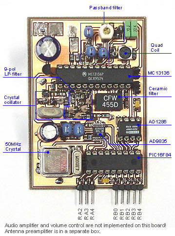
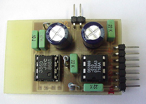
Hard ware
In the block diagram you can find many part as mixers, FM-modulator, RSSI unit and lot of other blocks.
For this project I have choosen a commonly used radio-circuit called MC13135 or MC13136. This circuit is not difficult to find.
The nice thing with this circuit is that it contains one oscillator, two mixers and FM-demodulator with RSSI indicator.
I will now go threw all part in the big schematic and explain them part by part. I will cut out picture from the main schematic so there
should not be any difference between them and the larg schematic.
Preamplifier
The preamplifier is based on a dualgate FET-transistor. I use BF990A, but you can also use BF991 or BF981. This preamplifier has to filter. One
at the input and one at the output. The voltage at gate 2 set the gain of the preamplifier. I have set the voltage to 4.5V wich will give
a high gain. Gate 1 is connected to L1 and C1. L1 and C1 is tuned to 80MHz. To match antenna impedance, I connect the antenna
to a tap point at the coil L1. This will give me better seletivity. You can experiment yourself where to connect the antenna tap for best performance.
The drain is also connected to a tuned LC circuit, L2 and C2. To match circuit impedance I have a tap point at coil L2. I have a tap 3 turns
from the +9V. Also here you can experiment to find the best performance.
The easiest way to tune this preamplifier is simply to adjust C1 and C2 for best RSSI and audio signals.
The current in the 100 ohm resistor should be about 8-15mA.
A good tip to you is to shield the preamplifier in a methalic box and drill holes so you can adjust the C1 and C2.
Be careful for static electricity, the FET is very sensitive and can be damage easy!
Crystal oscillator
The crystal oscillator is based on a colpitt oscillator. The inductance L1 and the resistor of 1k makes sure that the crystal oscillate
at the 3:d harmonic. In my case it is 45.18125MHz. In the mixer you will have many frequency products. One nice thing with this IC is
that there is an OSC-buffer at pin3. You can connect an oscilloscope or frequency counter to this pin and make sure you got a nice oscillation.
Passbandfilter
Most often you will find a 10.7 MHz ceramic filter at pin 18,19 and 20 (see datasheets). The ceramic filter is too sharp to use in this construction.
I needed a 2-3MHz wide filter so I just had to build one with passive components.
The signal from the fist mixer comes out at pin 20 and enter the filter. The 10p tunable capacitor (C3) is varible to tune the filter
for best performance. The output of this filter is DC blocked via the 10nF capacitor and is also loaded with the 390 ohm
resistor to match the impedance. At right you can see the frequency respons of this filter. As you can see this filter pass frequency
from 9 to 11MHz. The variable capacitor is set to 8.5 pF. This filter is not difficult to tune. You can ofcourse tune the passbandfilter
when the scanner is scanning. Most strong RF signal will pass this filter even if it is not tuned correctly.
What I did was to set the receiving frequency so the signal to the second mixer would end up in the middle of this passbandfilter.
As we calculated above the input to mixer 2 will vary from 9.455MHz to 11.455MHz and the center will therefor be 10.455MHz so the
DDS should be set to 10MHz. The receiving frequency will therefore be: 90.3625-10=80.3625MHz. I couln't find any station there so
what I did was to build a simple VCO (LC-oscillator see my VCO link). I feed the VCO with
an audio signal and I put a piece of wire at the output. I tuned this VCO oscillator to 80.3625MHz by listening to the receiver sound, and
then I simply measured the RSSI voltage with a voltage meter and tuned the passbandfilter for for best RSSI performance and sound.
The VCO is very handy to use when you tune the preamplifier. Just do as above and tune the capacitor in the preamplifier for
best RSSI level and sound.
DDS circuit with 9-pol lowpassfilter
The DDS circuit I use is AD9835. You can find info about it in my previous project.
The output from the DDS must be filtered becasue the DDS-DAC introduces additional spurs, which come from
three sources: intermodulation spurs due to non-linearities in
the DAC; a spur at the clock oscillator frequency due to clock
feed-through; and power supply noise. The DAC also faithfully
reproduces the aliases and harmonics that are unavoidable
products of the NCO due to the digital nature of the output.
The filter on the output of the DAC eliminates the clock feed
through, aliases due to the sampled nature of the NCO output
and most of the AM spurs are eliminated.
The pic at right shows the filter respons and as you can see the filter dropps fast after 12MHz. This filter is easy to build and needs no
tuning. I have choosen standard componets values. The resistors are choosen to match the DDS impedance.
The output frequency from this filter will be from 9 to 11MHz as I have mention earlier.
A/D circuit
Well, you can use any sitable A/D. I have found a circuit called AD1286. It is a 12 bit A/D with 8 pin. It has a seriel interface.
I like this A/D because it is fast and accurate and very simple to communicate with. It is common and cheap.
There is Ref pin for reference voltage. I use a simple voltage divider with a capacitor to set the Ref voltage at 2.5V.
The Vin+ is simply connected to the RSSI output at the RF-chip.
The RSSI from MC13136 can vary from 0.4V to 1.2V (see datasheets). You could change the voltage divider so the Ref voltage is
1.2V, it will give you 12bit full scale of the RSSI.
Audio unit and squelsh control
Lets have a look at the volume control and the amplifier. I like digital stuff so I have implemented a digital volume controling circuit.
Button 1 increase the volume and button 2 decrease the volume.
This circuit has 64 levels and it can be set with the pin UC (up) and DC (down) pin. The main CPU (PIC16F84 in
my case) control the volume. The squelsh control work in the same way. When the RSSI level indicate no radio-signal the volume control
will be in the bottom position (no sound) and the opposite when the RSSI indicates a radio-signal, then the volume will go up to the level you
desire.
I have measured the RSSI with a simple voltmeter and when I had no radio-signal the level was about 450mV and when I received a
radio signal, the RSSI went up to 900mV (I used a simple whip as antenna and I was indoors). There is a clear difference for the CPU
to deside if there is or not is a valid RF-signal.
The power-amplifier is the old fashion LM386 wich will give you a very good sound in the speaker.
How to program the PIC16F84 for different frequency
It is VERY difficult to make a software that suits everyone! I do have made a software for the PIC16F84 where you can set your
own scanning frequency and squelsh level.
I have made a scanning program that scann 5 channels and where you can preprogram the channel frequency yourself. The channels
are programmed into the EEPROM of the PIC circuit. All you need to do is to decide wich frequency you want and calculate the correct DDS values.
I will explain in detail how you calculate this.
When you program the PIC-circuit you can also set the EEPROM manually. Most often one never use the EEPROM,
but in this case we will.
The DDS need 4 byte (32bit) to set a frequency. The PIC has totally 64 byte EEPROM. The picture at right shows how to program the
EEPROM.
Each channel (scanning frequency) need 4 byte. If you look at adress 2 to 5 (Yellow area) you find the 4 byte for channel 0. Next
4 byte is for channel 1 (green area) and so on.
The first 2 adresses (Red area) is to set the squelsh trigging level. Here you can preset wich level you
want the squelsh to open. Example: I have measured the RSSI signal to 900mV at good RF-receiving. I want the squelsh to open when the RSSI level is 700mV.
Since the A/D ref is 2.5V and 12 bit (4096 levels) I can calculate what 700mV represent in hex number. (4096/2500)*700=1146 Dec => 047a Hex.
So I program adress 0 to 04 Hex and adress 1 to 7a Hex.
If the A/D value is higher than 047a Hex the volum control will open and present the audio.
How to calculate the frequency for the DDS
Lets say I want to receive at 79.6625MHz. I know the fist mixer mix the RF input with 90.3625MHz (becasue of the crystal I am using). The product will be 90.3625-79.6625=10.7MHz.
The DDS frequency should therefor be 10.7 - 0.455 = 10.245MHz.
Now we now the frequency!
The DDS use a 50MHz crystal as reference so the relation of the two frequency is : 10.245 / 50 = 0.2049
The resolution of the DDS is 232 and if we multiplicate that with the relation we will have :
232 *0.2049 = 880038799 => 34 75 53 8e Hex.
Adress 2 should contain : 34 Hex
Adress 3 should contain : 75 Hex
Adress 4 should contain : 53 Hex
Adress 5 should contain : 8e Hex
Channel 0 is will now be set to receive at 79.6625MHz.
Building and testing
To test this unit you should disconnect the Vin+ at the A/D from the RSSI. Connect the Vin+ at the A/D to +5V. This will trick the CPU
to believe that there is a radio-signal and the CPU will not scann. The audio will also be presented in the speaker as a nois.
(make sure you have turned up the volum).
You can now probe pin3 to make sure the crystal is working and you can probe pin6 to make sure the DDS is working at the right
frequency. Since the premplifier is a bit tricky to tune I recomment you first to test the unit without the preamplifier connected. Just connect
the antenna directly to the circuit. To test the audio unit you can disconnect the digital volume control from the radio circuit and connect
it to some other audio source you got, just to make sure it amplifies the sound.
Remember that if the Vin+ is not connected to +5V, the CPU might belive you have no signal and then it will turn off the sound
and keep the DDS scanning, and you don't want that when you are testing the receiver!
HEX-code for the PIC16F84 (INHX8M format) the file is zipped!
Final word
Maybe you won't build this exact construction, but you can always use the concept for any other frequency.
I hope I have given you some new ideas and knowledge. You can always mail me if there is anything unclear.
I wish you good luck with your projects and thanks for visit my page.
 Background
 Extra options
 How to program the PIC16F84 for different frequency