Direct Digital Synthesis (DDS)

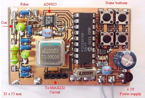
The purpose of this project is to learn about DDS circuit.
The AD9835 combines the Numerical Controlled Oscillator (NCO), COS Look-Up Table, Frequency and Phase Modulators, and a Digital-to-Analog Converter on a single integrated circuit.

With more easy words you can say that this circuit is a oscillator where the frequency can be programmed from 0 to 25 MHz with the resolution of 0.01Hz!
Here you will also be able to download controling software for your own projects.
This DDS project is also a pre-project for my Spectrum analyzer project.
All contribution to this page are most welcome!

Background


DDS stands for Direct-Digital Synthesis. This synthesizer is simply a circuit that can create a sine- wave signal from a reference crystal and a programable frequency-register. All this circuit needs is a reference oscillator (crystal) and some filter.
See fig above: A crystal oscillator (50MHz in my case) is connected to the input (Clock in) of the DDS.
The phase accumulator calculate the frequency you want the output to have. A sine memory map send data to the D/A and at the output you will have a sinus-signal with the desired (programmed) frequency.
You can program the output frequency from 0Hz to 50MHz, but according to the sampling theory (Shannon, Nyquist) practically, the output is limited to about 45% of the maximum clock rate at which the logic can be operated. This means that the sinus-output can reach from 0 Hz to about 25MHz with a 50MHz crystal. I think that is really good.
Inside the DDS is a programable divider wich divid the Clock in with 232 and multiply it with a programable register.
Example:
The highest resolution will therfore be: 50MHz / 232 => 0.011641532Hz.

This means that you can program the output from 0Hz to 25MHz with 0.011Hz step and have an almost perfect sinus output signal, WOW!

When can this be useful?


Lets say you want to build a 6M (50MHz) fine tuned receiver and maybe you want it to be a digital tuning. (See pic above). Now, the first mixer mix the input frequency with a crystall controlled frequency so from this mixer you will get an IF about 10MHz. Next mixer will mix the IF with the DDS frequency 0-20 MHz and the output is demodulated to an audio signal.
If you program the DDS so the output is almost 0 Hz you will receive at 40MHz and if you program the DDS so the output is 20MHz you will receive at 60MHz.
Conclusion: With the DDS you will now be able to tune the receiver from 40MHz to 60MHz. The smallest stepsize will be 0.011Hz. That is amazing!
The Registers in the DDS can be changed with a few micro seconds, so you can jump between different frequency really fast. Maybe you want to build a scanner wich scann really fast, the you should use a DDS. A PLL-synthesizer will never be as fast.

Maybe you want to build a sweep oscillator to tune your IF filter or crystal filter (0-25MHz), then a DDS is perfect for you. You can also use the DDS to build a programable low frequency tone generator.

My next DDS project will be a police scanner that scann from 79 to 81 MHz. It is only a few MHz and a DDS will really make it fast scanning. The nice with that project is that I dont need to find an exact 69MHz crystal for the first mixer since I can program the DDS.
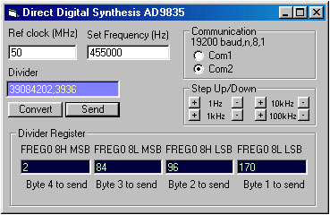
Now I have introduced you to DDS tecnology. If you want to know all the details you should go to this page : ddstutor.
I will now go on explain how you can build a controller for the DDS circuit AD9835. I will also explain the internal register and at the bottom You will be able to dowload some software to this project.

Internal Registers
I will now explain the internal registers and don't worry if you wont understand right away. You really don't need to understand all the registers and bits to be able to use my DDS construction. I will later show how you can connect a PIC between a computer and the DDS. I have implemented everyting into a PIC, so you only need to know how to handle RS232 on your computer to be able to set the desired frequency from the DDS. If you know how to program a PIC you won't have any problem to set the registers yourself. A good help is to download the datasheet and read more about the details.


The pic above shows the internal block in the chip. Lets start with the yellow part.
There are two 32 bits registers wich can set the divider ration FREQ 0 REG and FREQ 1 REG. You can choose wich register you want to be present for the phase accumulator by the register SELSRC (Select Source Bit). IF SELSRC is = 0 the selection of register is made by the FSELECT pin on the AD9835. IF SELSRC is = 1 the selection of register is made by the bit (internal register).
In most cases one only need 1 register, so I have choose to set the SELSRC = 0 and I choose to use FREQ 0 REG by conect the FSELECT pin to GND.

The blue part shows the phase register. There is 4 different registers wich all contains the phase of the signal. These register can also be selected by two pin on the ic or by two registers.
IF SELSRC is = 0 the selection of the phase registers are made by the PSEL 0 and PSEL 1 pins on the AD9835. IF SELSRC is = 1 the selection of the phase register is made by the bit (internal register).
I never need to change the phase, so I have set the SELSRC = 0 and conected the pins PSEL 0 and PSEL 1 to GND.
For futher data see the datasheets.
The green part is the hart of the DDS. It is here the sinus signal is built up.
The purple part is the controlling unit. FSYNC, SCLK and SDATA are for setting the registers.
FSYNC must go low to send data to the DDS. SCLK clocks data into the DDS and the SDATA is the data to the DDS.

How to load data into the registers
The table below shows the 32-Bit Frequency Word.
16 MSBs
16 LSBs
8 H MSBs
8 L MSBs
8 H LSBs
8 L LSBs

As you can see, you need four 8-bit data to get the 32 bit word. Within the AD9835, 16-bit transfers are used when loading the destination frequency/phase register. There are two modes for loading a register direct data transfer and a deferred data transfer. See the block diagram above.

Direct data transfer:
With a direct data transfer, the 8-bit word is loaded into the appropriate defer register (8 LSBs or 8 MSBs). Immediately following the loading of the defer register, the contents of the complete defer register are loaded into the 16-bit data register and the destination register is loaded on the next MCLK rising edge.

Deferred data transfer:
With a deferred data transfer, the 8-bit word is loaded into the defer register (8 LSBs or 8 MSBs) . However, this data is not loaded into the 16-bit data register so the destination register is not updated. The destination register will be uppdated when when a destination register is addressed.

This is just a summary about the registers. In the datasheets you can find the controlling words and register address and more details.

Hardware schematic


The hart of the interface is the PIC16F84 PIC-processor. MAX232 is a RS232-to-TTL converter. It convert the voltage level from the computer to 5/0V. The PIC is listening to the computer at pin 18. If the computer send something the PIC will receive it through this pin. When the PIC has received a complete package of information (I will come to this later) The PIC will set the internal registers in the AD9835. The baudrate must be 19200 baud, 1startbit, 1 stopbit and even paritet. It is also important the the crystal for the pic is 4.0MHz, because this set the baudrate.

The AD9835 circuit has a 50MHz oscillator connected at pin 6. It doesn't have to be 50MHz, but I want to use the full limit of this circuit. Pin 1,2 and 3 set the output current from the D/A in the circuit. According to the datasheets, the max output current is 4mA. With a 300 resistor I will get 0.004*300 = 1.2V. I have measured the output voltage and a low frequency I do have about 1.2V. The higher frequency, the lower output voltage. I will show you a table where I have made some measurements later on.
The system runs on 5V and the purpose of the two coils L1 and L2 are to filter the DC from disturbance. L2 separates the digital and analogue VCC. You can use any type of coils, just keep the inductance high (at least 10uH).

Troubble shooting:

Software


This DDS controller need 4 bytes (32bits) to set the desired frequency. The computer should send the 4 bytes with the LSB byte first and the 4:th byte will be the MSB byte.
How to calculate the 4 bytes:
If you use a 50MHz oscillator the smallest step will be 50.000.000 / 232 = 0.011641532 Hz
If you want a 1kHz signal you have to program the FREQ REG with 1000 / 0.011641532 = 85899 = $00014F8B
So the first byte should be $8B the next $4F the next $01 and the last byte $00
If you send these 4 bytes to the unit you will have 1kHz output from the DDS.
If you don't know how to make a computerprogram that can handle this, I can provide you with a window software. I can not put the software on this site because my www-free-space is shrinking. If you want the program that communicates with this DDS unit you can mail me and I will send it to you.

Output filter
At high frequency the shape of the output signal from the DDS is not perfect and there might be lots of overtones from the digitsl part. These disturbances should be filtered away. I will make my DDS work up to about 13 MHz so therefore I have made a 7 pol LP Butterworth filter to clear up the signal. Se figure below.

Filter schematic:


I have now added the 7 pol filter, see inside the gray dashed line. There is tree coils L3, L4 and L5. L4 is 3.0uH, but you can use 3.2uH also, the filter respons will not vary much. All capacitors should be 68pF. Since 3.2uH and 68pF is standard values you shouldn't have any problem to find them.

Remeber that this filter is designed to work upp to 14MHz and there is some ripple. If you want higher frequency or better flatness of the respons you must construct another filter. I have also noticed that the amplitude decrese with higher frequency. One could compensate this with the filter, but I will not use the output to any accurate measurement, just as a osc to a mixer.


Theoretical filter respons:


As you can see the filter is really flat between 7 and 14 MHz. It dropps then rappidly. There is a dip at 4Mhz, but since I will use the DDS from 8 to 12 MHz I don't mind.

Measured filter respons:

The pic below show the true output signal from my filter. I have measured the output with a 100MHz oscilloscope. As you can see the output is flat up to 11.5MHz and drops to 100mV at 12MHz. After 11.5MHz it dropps quit fast. This amplitude is enough to drive most mixers , but you might have to amplify the signal. The next section below shows one easy made amplifier.


Output Amplifier
Amplifiers can be made in many different ways. You can use transistors, Fet and or as I a (MMIC).
The MSA-0186 is a high performance silicon bipolar Monolithic Microwave Integrated Circuit (MMIC) housed in a low cost. This circuit only need a few components to give a 18dB amplification see figure below. This circuit has 4 input pins and is easy to solder, There are many other similar circuits on the market. The Rbias should be about 200 ohm at 9V. If you want you can add the coil (more than 1uH)
Click here to download the datasheet for msa0186.pdf

Some measurements:
Vcc = 9V
Rbias (ohm)
Id (mA)
RLoad (ohm)
Vout (mV RMS)
196
15.4
50
258
196
15.4
100
352
147
19.5
50
354
147
19.5
100
490


Windows Software
I can not put the software on this page because I need all the space for homepages. But if you want this software just mail me and I'll send it to you. It is 2.04Mega byte divided into two disk. The software is very simple! Enter the reference frequency (50MHz in my case), then you enter the desired output frequency. If you click convert you will see the content for the four registers. You will also see the divider rate. If you click Send you will send the four bytes down to the unit. There is also a simple step function when you can increase/decrease the frequency by a simple click.


Download the window and PIC16F84 program
dds.zip Click to download the zipped dds.hex program for the PIC16F84.

Download software
Download windows software
dds.zip (1.96Mb)
Click here to go to the software download page!


The PIC16F84 hex file is zipped in the file called dds.zip. You need to unzip this file and then you will have the dds.hex to program into the PIC.
Please report all problem you have and I will fix them.

I wish you good luck with your projects and thanks for visit my page.


Back to main Page  |  Contact Me  |  Cheap components

Copyright © Last modified on 16th Nov 2001.