This unit can divide input frequency with 1000 or 10.000 Poor man's counter
This project will turn your multimeter into a sensitive frequency counter with a wide counting range.
You can also use this project to upgrade your old frequency counter and extend the range up to 2.5GHz.
All contribution to this page are most welcome!

Background
Most multimeters can measure frequency, but they are not sensitive and the max frequency is not always so high.
The same problem can be found with older frequency counters.

This project will describe a prescaler which will work up to 2.5GHz and with very high input sensitivity.
The prescaler will divide the input frequency with either 1000 or 10.000.

The divided output signal is 0/5 volt and can be connected to your instrument as it is.
The divider ration is set by a jumper (switch).
A PIC 16F84 handle all communication to the prescaler.

Example:
I have a frequency of 100MHz.
I set the divider to 1000.
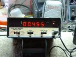
The output signal from the divider will now be 100e6/1000 = 100.000Hz.
My multimeter show me 100.0kHz
If I now change the divider to 10.000, the output will be 100e6/10000 = 10.000Hz.
My multimeter show me 10.0kHz

Conclusion:
Even if the prefix (kHz) is not correct on my multimeter, I will know that the measurement is MHz and I can see the reading.
A simple and easy way to measure frequency.

Click here to view a larger schematic 
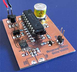
Hardware and schematic
The main part of this project is the PIC16F84 and a prescaler LMX2322.
The input of the LMX2322 is symmetrically at pin 7 and 8.
The input impedance is about 100 ohm and with R7 you form an input impedance of 50 ohm.
Transistor Q1 forms a buffer for the output frequency which is the divided signal.
The output is TTL level and can be directly connected to any instrument.
SW1 is the switch that set the divider ration.

  • If SW1 = Off the divider ration is 1000.

  • If SW1 = On the divider ration is 10.000.


  • PCB
    div1000.pdf PCB file for Poor man's counter (pdf).

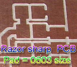
    Above you can download a (pdf) filer which is the black PCB.
    The PCB is mirrored because the printed side should be faced down the board during UV exposure.
    To the right you will find a pic showing the assembly of all components on the same board.
    This is how the real board should look when you are going to solder the components.
    It is a board made for surface mounted components, so the copper is on the top layer.

    Grey area is coppar and each component is draw in different colours all to make it easy to identify for you.
    The scale of the pdf is 1:1 and the picture at right is magnified with 4 times.
    Click on the picture to enlarge it.


    The desoldering wick is a flattened, braided copper sheath	Soldering the LMX2322
    Here comes the big challenge.
    Click here to see photo and read how to solder SOIC and smd components.
    The circuit is a fine pitch SO-IC circuit and this little bug can make your life miserable.
    Don't worry I will explain how to handle it. Use thin lead solder and a clean soldering tool.
    I start by fixate one leg on each side of the circuit and makes sure it is correct placed.
    Then I solder all other legs and I don't care if there will be any lead bridges.
    After that it is time to clean up and for that I use a "wick".
    The desoldering wick is a flattened, braided copper sheath looking for all the world like shielding on phono cord (except that the shielding is tinned) without the cord.
    I impregnate the wick with some rosin and place it over the legs and bridges of the circuit. The wick is then heated by the soldering iron, and the molten solder flows up the braid by capillary action.
    After that, all bridges will be gone and the circuit looks perfect.
    You can find wick and rosin at my component page.

    Purpose of resistor R5
    Before you solder R5 you should test the frequency counter.
    The input of the LMX2322 (prescaler) is very sensitive. When the input is not connected to any source, the circuit will pick up any RF noise and start to self oscillate.
    This behaviour can be used to test the circuit function in a simple way. When the power is on, the display should show something like 1.4-1.6 GHz.
    If so, you can be sure that the PLL is soldered correctly and working fine. To prevent self oscillation, R5 is added to the input stage.
    This will make the counter show 0 when no RF signal is applied. R5 will not affect RF signal or sensitivity of the frequency counter.

    Sensitivity of input signal
    Table below show my measurements of the sensitivity of this unit.
    This counter will work best when the input frequency is from 10 MHz to 2.5 GHz.
    Below you will see a table of some measurement I have made with an old frequency generator.
    I have also measured VCO:s at 2.0 -2.5 GHz perfectly.
    The input signal is terminated at the prescaler with 100 ohm and since the input impedance of the prescaler is 100 ohm you have a total input impedance of 50 ohm.

    Frequency (MHz)
    mV rms
    uW (into 50 ohm)
    dBm (into 50 ohm)
    60
    90
    160
    -8.0
    80
    60
    69
    -11.6
    100
    48
    46
    -13.3
    120
    40
    32
    -15.0
    140
    33
    22
    -16.6
    160
    27
    15
    -18.2
    180
    24
    12
    -19.2
    200
    24
    12
    -19.2
    220
    24
    12
    -19.2


    Download PIC16F84 programs (INHX8M format)
    Here you can download the software for this project. The zip file contains hex file made for this project.
    div1000.zip Software to Poor man's counter (the hex files are zipped!).


    Kit
    This project is no longer as KIT.
    All component for Poor man's counter (Click here to download component list.txt).
    The picture is magnified X 5 times and show you the high quality of the PCB. Rrazor sharp pads and lines!

    Final word
    In this part, I describes a very powerful frequency divider whith ration of 1000 and 10.000.
    You can always mail me if there is anything unclear.
    I wish you good luck with your projects and thanks for visit my page.


    Back to main Page  |  Contact Me  |  Cheap components

    Copyright © Last modified on 28 Jan 2007.