How a radio receiver work
On this page I will explain for you how a radio receiver works. Almost every receiver works in the same way.
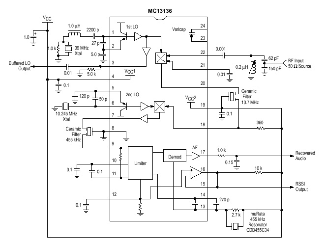
One of the circuit I use in my projects is the MC13135/MC13136. It is the second generation of single chip, dual conversion FM communication receivers developed
by Motorola. Major improvment in signal handling, RSSI and first oscillator operation have been made.
All contribution to this page are most welcome!
Function description
At pin 22 you will find the RF-input this is the antenna input connection. This receiver will receive at 49.7 MHz.
The RF signal will mix with the crystal oscillator (39MHz) pin 1 and 2. The product frequency 49.7-39 =10.7MHz will come out at pin 20.
A ceramic filter removes all other frequences except the 10.7MHz wich will enter at pin 18. Here you will find a new mixer wich will mix the 10.7MHz
with another crystall oscillator (10.245MHz) pin 5 and 6. The product frequence 10.7-10.245 =455kHz will come out at pin 7.
A ceramic filter removes all other frequences except the 455kHz wich will enter pin 9.
Now, you have tiny signal at 455kHz wich will vary a little around 455kHz depending on the FM-modulation (+/- some kiloherts).
This tiny signal must be amplified to a level where the audiosignal can be demodulated from the RF-signal.
The tiny RF-signal will also vary in strength depending how close you are to the transmitter. What you want is a constant level
wich is not depending on the distance to the transmitter.
So, there is a amplifying-limiting stage at pin 9,10,11, and 12. This stage amplify the tiny RF-singal to a constant safe level where the
demodulator can demodulate the audio-signal. This stage could be called a voltage controlled gain-stage. As you might understand, the
closer you are to a transmitter the strong the RF-signal will be, and in such case the limiter will not have to gain the signal so much.
The amplifier has a very wide amplifying area, from 100 to some milion times.
The voltage to control the gain is called (Received Signal Strength Indicator) RSSI and can be found at pin 12 and 15.
Here you will find a voltage from 0.4 - 1.2 volt.
Lowest level is 0.4 V means that the RF-voltage is 0.22uV and
Highest level is 1.2 V means that the RF-voltage is 2.3mV (very high) .
The RSSI output signal is used to turn the audio amplifier on/off. When the RSSI is low you have a very weak signal or
maybe no signal at all, and you don't want to hear the noise, so the speaker should be turned off.
When the RSSI level rise you will probably have a RF-signal and the AF-speaker should be turned on to let you hear the sound.
The RSSI signal can also be connected to a analogue voltmeter to display the Signal Strength.
I will continue to explain the receiver. At pin 13 and 14 is a ceramic filter or a "quad coil" connected.
This componet will bring out the sound from the 455KHz IF-signal. If you want to learn more about this
look at my quad coil page.
At pin 17 the recovered audio-signal is amplifier to 200mV.