Click on the photo to see full picture.
Superior TV-tuner receiver.
Do you want to tune in other galaxy? No problem!
To everybody joy, I have finally improved the Super Scanner.
This new receiver has superior performance and still it is very
simple to build. You will not have difficulty to find components either.

All contribution to this page are most welcome!

Background
The receivers I have build around the Tv tuners has been very popular,
so I just had to take my tuner projects to a new level. (how many can there be?)
The MC13136 circuit is not easy to find so I have replaced it with a new receiver circuit called SA615.
This is a basic FM receiver with very good performance and sensitivity.
The Radio Sky tuned to 408MHz In my super receiver I used a DDS to fine tune the receiver, but in this project
I replaced it with a PLL synthesizer. The advantage with a PLL are:

  • Less components
  • Much cheaper
  • Easier to build
  • Easier to control


  • Since I won't tune finer than 2500Hz I have decided to let the smallest step be 2500Hz.
    If you want smaller step you just have to work a bit on the software (no Hardware changed needed). I find 2500Hz to bee good for me.
    I will not go into details about the tuner because you can read about that in my previous project so let's jump into the project, shall we.
    Below I will blurr quit lot about tuner steps and PLL synthesizer, so take your pills and hold on to your chair.

    Block schematic
    The picture at right show you the basic block of this TV tuner receiver.
    I will give you a overview and later I will go into all the details.
    If we follow the signal into the antenna we comes to the TV tuner.
    A TV tuner is actually just a down converter for RF signals.
    It can be programmed to any frequency from 46 to 860MHz and it down convert the RF signal to an IF signal which should be about 33 - 39MHz (Details later!).

    The signal then leaves the TV tuner and enter a SAW filter. This is a sharp filter that reject all frequencies except 33-39MHz. As you understand the SAW filter is wide because a TV signal is about 6MHz wide.
    I will still use this filter since I can't find any narrow filter for this frequency and it works good.
    After the filter you will find a FM receiver with excellent performance.
    It is a FM receiver and it is tuned to the IF frequency and demodulates the IF signal to an audio signal.
    Under the FM receiver you will find a PLL Synthesizer, and now you wonder why?
    The frequency is set by the TV tuner isn't it!
    Well, YES and NO.
    The TV tuner will set the large step of tuning and the PLL synthesizer of the FM receiver will set the fine tuning.
    The picture below will explain the tuner step size and the reason of using the extra PLL synthesizer.

    Tuner stepsize
    The picture show you three radiosignal called Station 1 to Station 3.
    The X axle is the frequency and the Y axle is the power of the signal.
    I have not printed the exact frequency because it is not interesting to show. The important part is that you see the 62500 Hz steps
    at the X axle. The tuner is digitally controlled (actually it is also PLL synthesized controlled) and the step size is set to 62500Hz.

    If you look at Station 1 you will se that carrier frequency (blue line) is exactly over one step of the tuner and the signal will be received perfectly. The same happens with Station 2 because it is exactly one tuner step up (+ 62500). Until now everything works great, but we end up with trouble at Station 3.

    The Station 3 is not 62500 up in frequency it is only 37500 from the previous frequency.
    If we increase the tuner one step we will have gone to far up in frequency and that will not give us any good reception.
    This will happen in reality also because radio signals exist everywhere between the TV tuner steps. Hmm…..what should we do.

    As you can see the deviation of the frequency is -25000Hz (pink colour) to the next step.
    This means that if we increase the tuner another step we will have to compensate the ( -25000Hz) some where else.
    The correction will be done by the PLL synthesizer connected to the FM radio receiver circuit.

    Conclusion:
    If we want to receive within the steps in the TV tuner (62500Hz) we will have to compensate the frequency deviation
    with the PLL synthesizer at the FM radio receiver.


    Some words about SAW filter
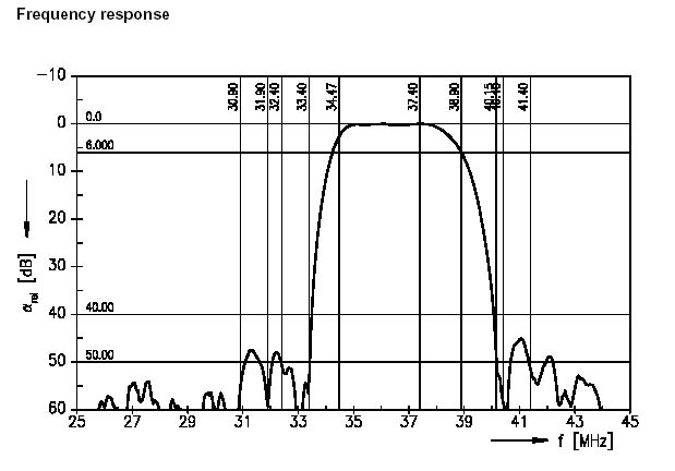
    Before we go future I want you to look at the filter shape of the SAW filter.
    There are some part you need to see before we go on. Click picture at right to see the filter shape.
    This picture show you the frequency response out from the SAW filter. You see that the filter only attenuate the signal 6dB from 35 to 39 MHz and around 37 you have no attenuation at all ( 0dB). That is all!

    Are you ready for some calculations?

    Calculation
    I have decided the oscillator frequency of the FM receiver to be 38.9MHz.
    See figure at right. This FM receiver has an IF frequency of 455kHz and that means it will receive RF signal at 38.9MHz ±455kHz. That means two places.
    One reception will be at 38.445MHz and the other will be at 39.335MHz.

    This is not good you think. You want only one station to be received.
    You are right, look now again at the SAW filter. At 38.445MHz the filter will attenuate 3dB but at 39.335MHz the filter will attenuate 25-30 dB or even more depending on the filter used.
    Great, this means that one side will be filtered away and the 38.445 MHz signal will pass and be demodulated.
    Conclusion:
    If we set the FM receiver oscillator to 38.9MHz the receiver will only receive incoming signal at 38.445MHz.

    Receiving examples
    Example: I want to receive at 86.555MHz (Checkout the Software below)
    RF TV tuner = VCO Tvtuner - RF FM receiver
    If we change place we get:
    VCO Tvtuner = RF TV tuner + RF FM receiver
    and number of tuner step are:
    VCO Tvtuner/ 62500 = number of step

    So, lets put some numbers into the formula:
    RF TV tuner = 86.555 MHz
    RF FM receiver = 38.445 MHz
    Then the VCO Tvtuner = 86.555 + 38.445 = 125 MHz

    125e6/62500 = 2000 step exactly…great!

    What happens if the frequency is 86.580 MHz then?
    Let's calculate it again:

    RF TV tuner = 86.580 MHz
    RF FM receiver = 38.445 MHz
    Then the VCO Tvtuner = 86.580 + 38.445 = 125.025 MHz
    125.025e6/62500 = 2000.4 steps
    Since the tuner only can't jump in decimal steps, the tuner will not reach this frequency!

    Hmmm…
    If we still set the TV tuner step to 2000 the VCO Tvtuner will be 2000 *62500 = 125MHz.
    Since we wanted the RF TV tuner to be = 86.58 MHz
    The RF FM receiver must be 125 - 86.580 = 38.420 MHz
    As you now see the frequency is 38.429MHz (-25000Hz) from the 38.445MHz.
    To correct this deviation we use the PLL system to change the receiving frequency from 38.445MHz to 38.429MHz and now we have perfect reception.

    Conclusion:
    What we did above was to trying to reach the frequency (86.580 MHz) but we soon realised that the frequency was between two tuner steps. We set the tuner and corrected the deviation with the PLL synthesizer of the FM receiver.

    Are your brain all blurry now?
    Good, let's move on..….smiling*

    Deviation control by PLL synthesizer
    Let's discuss a bit about the deviation control.
    The picture at right show you a frequency graph.
    The TV tuner can be set to two frequencies represented by "Step n" and "Step n+1". The spacing is 62500Hz since this is the smallest step size of the TV tuner.

    In this graph you will find that there is a radio signal between the two steps. To receive this signal we have to set the TV tuner either to
    "step n" or "step n+1" and then correct the deviation.
    If we set the tuner to "step n" we will have to correct the frequency with +31250Hz but if we set the tuner to "stepn+1" we will have to correct the frequency with -31250Hz.

    RULE:
    I have decided that the absolute (no sign) deviation is NOT allowed to be greater than 31250Hz.
    Example from above
    RF TV tuner = 86.580 MHz
    RF FM receiver = 38.445 MHz
    Then the VCO Tvtuner = 86.580 + 38.445 = 125.025 MHz
    125.025e6/62500 = 2000.4 steps

    If we set the step to 2000 we will have to correct the PLL synthesizer with:
    2000 steps will give 2000*62500 = 125MHz and 125.0-86.58 = 38.42MHz the deviation will be 38.42-38.445 = -25000Hz

    If we set the step to 2001 we will have to correct the PLL synthesizer with:
    2001 steps will give 2001*62500 = 125.0625MHz and 125.0625-86.58 = 38.4825MHz the deviation will be 38.4825-38.445 = +37500Hz

    Results:
  • 2000 steps gives = -25000Hz deviation

  • 2001 steps gives = +37500Hz deviation


  • From my rule I will not accept the +37500Hz solution!
    I think we are ready discussing tuner steps and PLL synthesizer correction.

    Lets have a look at the schematic
    Click on the schematic at right to see the complete schematic.

    Tuner
    At the left corner at top you see the UV916 tuner.
    Of course you can use any tuner you have as long as it is digital and you know how to control it.
    You need 3 different voltages to make it work.
  • +5V for digital and analogue unit.
  • +12V for preamplifier, AGC and band switching.
  • +33V for tuning.


  • The AGC input should be 6V or higher to give good gain. The tuner is controlled by two wires, SDA and SCL.
    The interface is called I2C and you can find detail about the interface on internet or at my other projects.
    I have marked the SDA and SCL in green flags on the schematic because they will be input connection on my PCB board. The output of the tuner (called IF) is connected to the SAW filter.
    You can use any saw filter you have found in some TV or VCR. The output of the SAW filter is then connected to the input of the radio receiver circuit.

    SA615
    Lets focus a bit on the radio receiver.
    This receiver use two 455kHz ceramic filter in the IF part.
    If you try to receive a wide FM signal with a narrow band filter you will only hear distorted audio.
    If you use wide filter you will have bad reception and sound quality with narrow band signals.
    So therefore, I have added in my hardware (not on the schematic) a relay switch between two filter types, one for narrow FM and one for wide FM. I use a two poles relay to change which filter to be connected to the radio circuit.
    The radio circuit also has internal FM demodulator to bring out the audio from the FM RF signal and there is a RSSI meter to tell the signal strength. The circuit also implement an oscillator. The oscillator can be found at pin 3 and 4.

    This oscillator is a LC oscillator and the I have made it voltage controlled by adding a varicap BB139.
    L2 is a air wounded coil with 12 turns and 6.5mm diameter. Together with the 15pF and the two 22pF at pin 3,4 you have am LC unit.
    The BB139 varicap will contribute with a small capacitans togheter with the 6.8pF (in serial) to the LC unit. Since the varicap will change capacitance dependent on the voltage over it (Vtune) you get a voltage controlled oscillator (VCO).

    PLL synthesizer LMX2306
    As we discusses earlier, the PLL probe the oscillator to measure the frequency and regulate the Vtune voltage to lock the oscillator.
    The probing of the oscillator is done with a second coil L3 which pick up some of the energy. L3 must be close to the main coil L2 to pick up enough energy for the LMX2306 circuit. The output of the PLL goes to a RC filter to obtain the Vtune voltage, which then feed the varicap and there you got it!

    The complete block
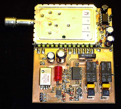
    The picture at right show you the complete receiver as a unit.
    you can see the five input controlling signals (green) at left side.
    Three for the PLL and two for the tuner. The unit consist of a LMX2306, tuner UV916, SAW filter and a SA615 radio receiver).
    The output from the unit is audio and RSSI strength meter.

    The unit also need some power supply to work.
    +5V, +12V and +33V will do the job.
    The +33V is the tuning voltage and draw very little current so any small step up converter will work. Try to make the ripple as low as possible in the step up converter. The cleaner DC the better.

    The tuner also need some kind of antenna to work.
    Most tuner use 75 ohm impedance wire and dipole antenna.

    I also have an extra input (SW) to control which IF filter to use.
    Wide FM or Narrow FM. It is basically two relay which simply switches the IF signal between two different types of ceramic filters (different bandwidth). I have not put this in the schematic.

    Software
    Below I will show you the software I have made to control this receiver unit.
    This software is very basic and I have not implemented so much to do.
    The software will show you all registers and help you to understand how it all works.


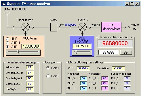
    Download windows software
    superior_tuner_software.zip (1.90Mb)
    Click here to go to the software download page!

    There are only two way you can set the receiving frequency.
  • Using the two sliders, one for the tuner (orange box) and one for the PLL (blue box).

  • Entering the wanted frequency and pressing button "set".


  • When you change the frequency all register will be updated and you can read the tuner VCO frequency, the
    PLL VCO frequency
    , the IF frequency and you can see how the internal register in the tuner and the PLL.
    The TV-tuner has 5 internal registers and specially the Dividerbyte 1 and Dividerbyte 2 changes.

    The PLL has 3 register R, N and a Function register.
    All will be changed when different frequencies are set.
    If you wish to read more about the internal registers I advice you to go to this link: RC Receiver for air plane and read more.
    If you have questions please write to me Me
    (Option: You can change the Addressbyte,Controlbyte and Portbyte by clicking on it)

    Computer interface (RS232 communication)
    Click on the pic to see a larger schematic. The schematic at right show you the RS232 communication adapter for the software to the tuner/PLL unit.
    It is a PIC16F870 connected with a RS232 to TTL converter.
    If you do not have this circuit you can easy build a converter with a transistor as the dotted square shows.
    I run my system on windows millennium, 98, 95, so I can not say if it works on XP.
    Hook it up with the software and have fun.


    Download PIC16F870 program (INHX8M format)
    tuner_III.zip Tuner program (the hex file is zipped!).

    Final word
    I hope this project has given you some new ideas and understanding.
    You can always mail me if there is anything unclear.

    I wish you good luck with your projects and thanks for visit my page.


    Back to main Page  |  Contact Me  |  Cheap components

    Copyright © Last modified on 23 Dec 2004.