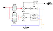
 VCR and TV-tuners
Block diagram
VCR and TV-tuners
Block diagram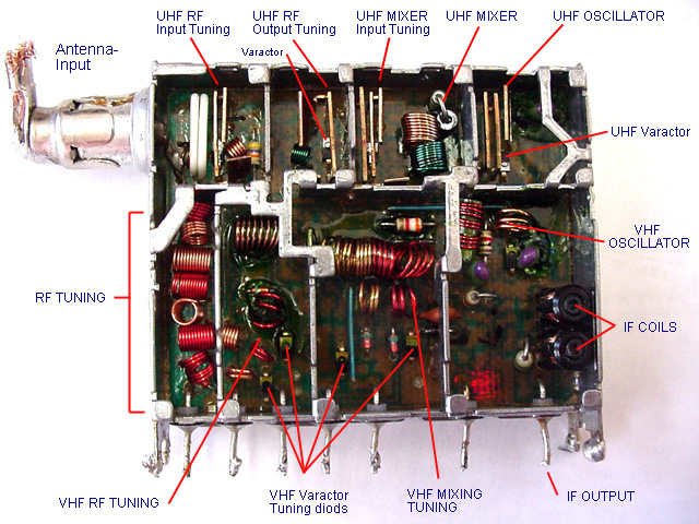 Front
Front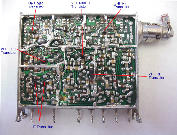 Back
Back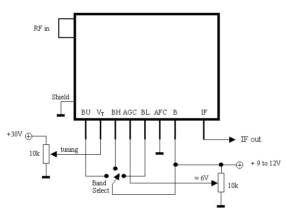 The connection to the tuner
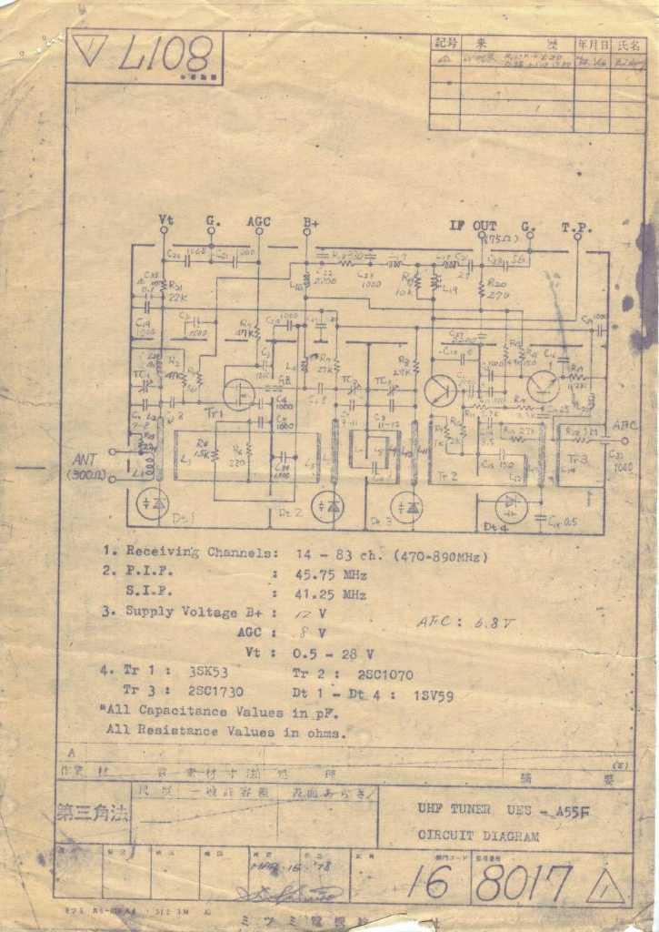 The scematic of a tuner
| |
|
||
| |
|
|
|
| |
|
|
|
 Comments to the pic at right:
| BAND | P0 | P1 | P2 | P3 | P4 | P5 | P6 | P7 |
| LOW BAND | X | X | X | 0 | 0 | 1 | 1 | 0 |
| MID BAND | X | X | X | 0 | 1 | 0 | 1 | 0 |
| HIGH BAND | X | X | X | 0 | 1 | 1 | 0 | 0 |
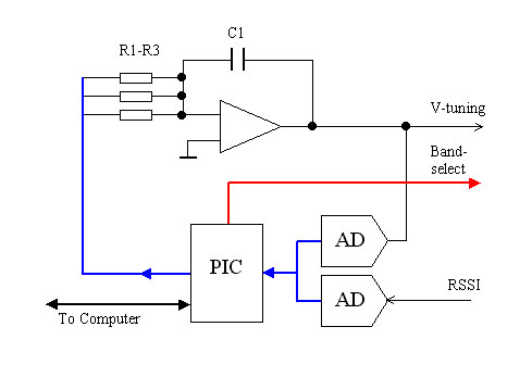 The sweep voltage is constructed around an OP-integrator. The OP works with +/- 18V so the V-tuning will have a range from
0 to 36 volt. The Integration time depends on the capacitor c1 and the total resistance from R1 to R3.
The sweep voltage is constructed around an OP-integrator. The OP works with +/- 18V so the V-tuning will have a range from
0 to 36 volt. The Integration time depends on the capacitor c1 and the total resistance from R1 to R3.