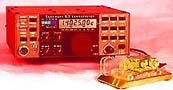
50 MHz crystal controlled transmitter II
This is a 3-transistor transmitter. This unit has many advantage.
The transmitter use a crystal 46.515MHz to hold a steady frequency.
The frequency can be fine-tuned by some 100kHz.
The transmitter can send data and audio-signal with +/- 10kHz FM modulation.
The output power is about 25mW into 50 ohm.
All contribution to this page are most welcome!
Background
This transmitter is a bit more complicated than model nr 1, still it is not so difficult to build and to tune.
with the 1 transistor transmitter I had really difficult to tune the transmitting frequency to match the receiver. I could not modulate the signal
much, just a few hundred Hertz. So the work contiuned. After some days I have come up with a very nice
piece of transmitter. This unit oscillate at the fundamental frequency (15.6566MHz) and a frequency trippler has been added.
Finally a power amplifier boost up the signal to the output.
The transmitting frequency can bee changed quit lot (100kHz), so the unit can be matched really good to the receiver. The
frequency can also be changed by applying a DC voltage to the input. The frequency deviation can be +/- 10kHz.
I will continue to build more and more powerfull transmitters. I have measured the output power to 25mW into 50 ohm.
The interesting part will be how long distance I can transmitt, and the overal performance of this unit.
The transmitter will work fine from 40 to 50 MHz, so if you don't have the 15.6566MHz (wich you most probably don't have) you
can use others.
The receiver for this project can be found here!
Scheamtic
The crystal I used is a 3:th overtone crystal. The coil L1 is a slug tuned coil. The primary winding is 8 turns and the second winding is 2 turn. The inductance in the primary winding is about 800nH.
L1 and C1 should be in resonance at 47MHz. The number of turns is dependent on type of coil you have. You will have best performance
when the "ferrite tuning slug" is at the bottom of the CAN, because you will then have the best couppling between the two
windings. Do like this: Wind primary and secondary winding on the core and turn the slug to the bottom of the CAN. If you can, measure
the inductance in the primary winding. It should be around 800nH. Attach a oscilloscope to the colector of the NPN transistor or to the second winding.
You should see an oscillation. Tune C1 until you find the 3:d overtone. You won't get a perfect signal at 47MHz. You will probably
find a very jumpy signal because of other harmonic frequencies. Don't mind that, just try to tune until you find some proper signal,
anyhow you will know that the oscillator works.
L2 and C2 help to clear up the 47MHz signal. L2 should be 300-700nH also a tunable coil. C1 and C2 should be in resonans at 47MHz.
I measured L2 and C2 in my construction and come upp with L2=476nH and C2=10pF.
The FET transistor is a voltage follower with very high imput impedance and low output impedance. You can attach an oscilloscope
at the source of BF245B. You should find a much better 47MHz signal here. Now, tune L2 and C2 until you reach a nice shaped signal with
max amplitude. Tune also L1 and C1 for best performance.
The last stage is a power amplifier. This unit doesn't need any tuning. I guess you can use many different type of transistors here.
I have used the BFG97 and it gives quit good power. I haven't been experimenting much with other types. With P1 you can set the current in the
transistor. You will have to experimient to find a suitable working current. I replaced this pot with a resistor of 7.5k.
You can also experimtent with resistor R2. The lowe value the higher current consumption and the more output power.
In my construction I shortcircuited this resistor. Be careful, the transistor can be hot!
The finetuning of the transmitting frequency is made with L3. This is also a tunable coil.
The inductance of this coil can be changed from
2-8uH. The exact value of L3 at 50MHz was 6.8uH in my experiment. You will have to play a bit to find the best inductance range for you transmitter. Just connect a frequency counter to the output
and tune L1 to the desired frequency. You can easy change the frequency some 100kHz. To match the receiver you should start the receiver and then tune the transmitter until you reach
the best signal from the receiver, then you will know that the two units are in perfect match.
To transmit audio
If you want to transmit audio you must remember that the varicap wont work with negativ voltage. The audio signal must be on a DC
level. For example at 2.9V. You might have to play a bit with the DC voltage. Since the capacitance in the varicap changes most
at lower voltage you will get more modulation the lover the DC leve you have. The pic below show how to build such a unit.
The Frequence Modulation is caused by a varicap diod BB132. The capacitance of this diod will change according to the input voltage and
thereby change the oscillation frequency.
PI network
The power amplifier will give highest output power when the impedance is low (See the power table below).
A PI filter will transform the antenna load to a much lower impedance. The result will be that the output power will
be higher, even for impedances above 50 ohm.
Table below shows some testresult of output power from the PI filter into different impedances.
Connect the "INPUT" to the output of the poweramplifier and replace the dummy load with an antenna.
Both capacitor should be tunable. Tune the two capacitor for best performance.
Output power
Impedance
Power (mW)
50 ohm
39.2mW
100 ohm
31.3mW
200 ohm
24.2mW
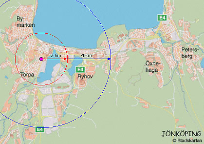
Performance in city enviroment
What I did was to connect a 60cm long wire to the output as antenna. I put the transmitter in my appartment and went out
and into the park outside. At 300 meter I had a very good signal. I jumped into my car and drow away. I live in a city, so
the buildings decreased the transmitting range very much. I still could hear the signal at 2000 meter away. In one direction of my appartment
is a small lake and not so many building. Finally I drow away 4km (4000m) in that direction (clear path) and I still could hear the signal.
With a proper antenna and som matching I guess you can improve the transmitting range.
CITY MAP
Inside the red circle the signal was really good even in the town. The radie of the circle is about 2km.
The blue circle shows the transmitting range if there is a clear path for the signal. The radie is about 4 km.
B.T.W. Along the big lake "Vättern" we have a really nice beach, specilally in the summertime...*big smiling*
 50 MHz crystal controlled transmitter II