VCO tester and logger
This project will help you to test VCOs.
You will be able to test VCOs and plot the VCO frequency range.
I have developed a software which will help you to control the measurement.
You can also use this software to control any PLL system based on LMX2322.
The PIC always remember the last programmed frequency.
After power up, the PIC always set the VCO to last used frequency.
This function make this unit able to be used as a stand alone RF generator.
The hardware is very simple and is based on the PCB for the GPS.
All contribution to this page are most welcome!
Background
Very often I find VCOs which has no label or datasheet.
I need a simple tool to test VCO and measure the VCO-range.
I also needed a software that could control a PLL (LMX2322).
In my GPS project I had developed a PCB which had a PIC16F870, VCO and a LMX2322 PLL onboard.
If I could control this unit with a software I could add any VCO to the PCB for testing.
The hardware was pretty basic since it was already developed, but the software was a bit more tricky.
After many days and many cups of coffee I was ready with the program.
I will now explain what you can do with the software and then I will explain how simple the hardware is.
Software
First lest see what this software can do.
Features:
Control the PLL LMX2322
Sweep frequency from 10 MHz to 2.5 GHz
Adjustable step size
Display PLL Register data
Display VCO Frequency
Display VCO voltage
Export data to Excel
Manually set PLL
PIC always remember last programmed frequency
How to control and use the software
First and all, you should set the Com port you use for the hardware. It is through this port all data will be transferred to and from the hardware (more details later).
In this case I use Com1.
In the Auto scan frame, you can set all option for the VCO sweep. I set my start to 830 MHz and then the end to 950 MHz.
The Ref freq is the Reference frequency of the hardware.
In this case it is 16.8 MHz crystal oscillator.
The default Step size is 0.1 MHz = 100kHz. You can change this with the <> buttons if you wish.
You can also magnify the step (not the step size) with the control buttons X1, X10 and X100. This will make the sweep go faster.
In my case, I used X100 and the step size was 100 kHz, so the frequency jump will be 100 * 100 kHz = 10 MHz.
I then pressed the Start scanning button, and the sweep starts.
If you now look in the information frame called Freq(MHz)-PLL voltage (V) to the left side, you can see that the frequency increment is 10 MHz for each measurement starting at 830 and ends at 950.
Above the information frame you will see the actual frequency and voltage during VCO measurement.
You will also see the voltage with the analogue indicator.
As you can see of the measured data, the voltage to the PLL goes from 0.36V to 3.28V.
This is the controlling voltage applied to the VCO to make the VCO frequency go from 830 MHz to 950 MHz.
With this software you can export data to Excel to print a nice graph. press the button File name and choose the prepared xls filed called vco.xls. (This files comes with the software package).
Then press the button called Export to Excel, and your data will be transferred to the Excel sheet with the graph. Do not forget to save the file to another name than vco!
Below you will see the Excel graph for this VCO.
The final option in the software is the Set frequency manually button. Enter a frequency into the box and click the button. The PLL will lock the VCO to the desired frequency as long as it is within the VCO range.
Excel Graph
In the graph you can see that I sweep from 800 MHz to 1050 MHz. The VCO tuning voltage went from 0 to +5V.
Hardware and schematic
This hardware is exactly the same as the GPS kit except of the VCO and the RS232 communication.
The Main part of this project is a VCO, PIC16F870 and a PLL LMX2322.
The PIC control the PLL through LE, Data and clock input and set the PLL to lock the VCO to desired frequency.
A feedback system of R4 and C7 feed the PLL with RF frequency.
X1 is a VCTCXO oscillator which acts as reference frequency.
It feed both the PLL and the PIC.
A pot P1 is added to fine tune the output frequency. X1 is a very stable and exact oscillator.
You will achieve best performance from the unit if X1 is calibrated with a frequency counter.
Still, the VCTCXO is so exact that the unit will work even if X1 is not tuned.
The PIC will control the VCO with a tuning voltage.
The voltage is built up from the PLL filter R6, C3 and C12.
The voltage from C3 should be feed back to pin 2 of the PIC16F870. A small piece of wire will do the job.
This is the tuning voltage of the VCO, which will be sent back to the windows software.
At pin 13 of the PIC you have an output which can be used for modulating the VCO, but it is not active in this software.
The output of the VCO is feed to a dummy load of 50 ohm (100//100). Some VCO has an internal serial capacitor, but it can be good to use a serial capacitor to prevent DC. I use 1nF.
A diode D1 is added to indicate that the PIC is alive and kicking. The diode will light every time data is transfered to the computer
The routing and type of PCB will affect the system very much with stray inductance's and capacitance's.
To the left side you can see how I have added a MAX232 circuit which convert RS232 to TTL. Data is transfered through pin 17 and 18 of the PIC to the com port of the computer.
PCB and modification
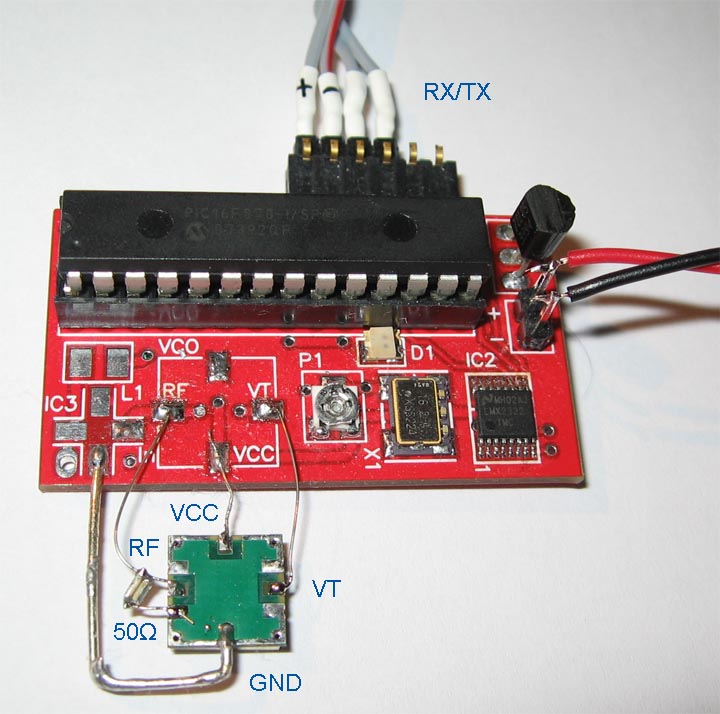
Below you will see how I have modified my GPS kit to become a VCO tester.
I have added a external RS232 to TTL converter (RX/TX) and I have added wires to my external VCO.
The VCO needs ground (GND), +5V (VCC), VT (tuning voltage) and RF (RF out).I take the ground from IC3.
In the picture you can see how I have added the dummy resistors (100//100) close to the VCO. The dummy is placed from ground to the RF output.
This is done because the VCO under test is working at GHz range and in those cases the dummy must be close to the VCO output.
This VCO has an internal capacitor at its output, so I do not need any external serial capacitor (1nF).
The IC3 and L1 is are not used on the PCB since they have no function for this project.
Modification
Below I sumersie the modification you need to do with the GPS KIT to get a VCO tester:
Connect a wire from C3 positive side to RA0 (pin 2) PIC16F870.
Add a RS232 to TTL converter (MAX232 or equal circuit) between computer and pin 17 and 18 of PIC16F870
Connect your VCO to GND, VCC, VT and RF.
I advice you to add a 50 ohm dummy close to the output as I have done. Remember that sometime you also need a serial capacitor with the dummy (see schematic).
Assembly
The assembly of this KIT is very simple.
Since this project is almost the same as the GPS I advice you to follow the assembly in the GPS KIT by clicking here.
KIT
I have put together a modified KIT for this project. The KIT is a GPS jammer KIT without VCO and IC3. Therefore the KIT is reduced in price. The KIT does not have RS232 converter, you have to add that separately.
Trouble Shooting section
If you get a problem with your unit, you might find this section helpful.
My PIC16F870 is not working and I get no blink from the diode D1!
Make sure you have placed the PIC in correct way.
Make sure you have + 5V to pin 20 of the PIC.
You should test that the Reset (pin 1) goes high when power is turned on.
Make sure you have 16.8MHz oscillation on pin 10.
(You can check this with an oscilloscope)
Check that the diode is placed in correct way.
I often use a small speaker or piezo element and listen to the signals at pin 12, 14, 15.
You should hear clicking sound or beeping tone once per second.
I get 0V or +5V over capacitor C3 !
Your PLL system is probably not locking.
Make sure you have placed IC2 correct and that you have proper soldering.
Measure that you have reference frequency on pin 1 IC2.
Make sure you have placed VCO correct and solder it well.
Check all other parts involving the PLL filter.
Final word
In this project I explain how I modify my GPS project to become a very useful tool to test VCO:s
The project may be a small one, but still it is a very nice tool to have.
Thanks for your time…