Click here to view a larger photo 
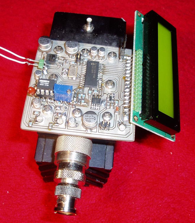
30 W Digital Wattmeter for RF (0-500MHz)
This project will explain how I build my new wattmeter.
This watt meter will be able to measure power from 300nW to 30W @ (0-500MHz).
This wattmeter is based up on a dummy load of 50 ohm which can handle 50W.
The measurement will be displayed in Watt on a 2x16 Char display.
The unit is very accurate, fast and easy to build.
All contribution to this page are most welcome!

Background
This watt meter project is very similar to my last wattmeter project. The main reason I made a new project is becasue I needed a unit which could handle higher power than 1W. I found a 50 ohm dummy load which could take 50W of power. Of course I could use attenuates for my 1W meter, but I prefered to build a new unit. The new thing with this project is that it will only display the power in Watt on the LCD display. This means that I will not need so many EEPROM to store display data (more about this later).
First we need to update our knowledge how to measure RF power: Some figures and text comes from my last wattmeter project, but it can be good to read it to remember.
How you calculate power


Above you can see a AC generator and a resistor of 50 ohm. A current will flow in the circuit and you can easy calculate the effect which will be consumed by the resistor. The effect will be transformed into heat. In the blue frame you can see how I calculate the power to 20mW. The red frame show how you can calculate the power into dBm, which which stand for decibels above 1 mW in 50 ohm, written dBm.
In the green table at rigth I have calculated some power into PdBm.

Block diagram


The input power is measured by the circuit AD8307. A resistor ladder will divide down the power to proper range for the AD8307 circuit. An A/D converter of 12 bit convert the analogue output from the AD8307 to a digital number. Since the AD is a12 bit A/D you will have 4096 combinations. The output values will be from 0 to 4095. Since the AD8307 gives a analogue voltage which represent the (dBm) of the input power, we need to recalculate the value to get the power in watt. The dBm is a logarithmic scale and that would include lot of math (floating point in the PIC processor) so I have chosen the easy way and used a lookup table instead. It is memory bank containing all the display text. I have pre-calculated all the display text for each A/D value. The output values from the AD (0 to 4095) points to a direction in the memory where the actual display text value is stored. The text will be fetched and presented on the display.

The advantage of using a memory map is that it will be easy to build, I can implement prefix in the text, it will be fast and it will work!
In reality I will use 1 EEPROM of 32k. The EEPROM is cheap but there is one tricky thing to do. The memory table must be programmed into the EEPROM before it can be used. You simply connect a RS232 cable to a computer and use a program I will support you with. This program will handle everything, just start the program and go make yourself a cup of coffee. Every memory cell will take 10-20ms to burn so it will take 10-15min.
Once the EEPROM has been programmed you will not have to do this again.

Hardware and schematic
Click here to view a larger schematic Let's look at the schematic at the RF-Input.
Directly connected over the input is a 50 ohm (dummy) resistor which can handle 50w.
Then you will see 5 resistors forming a voltage divider to the AD8307.
The resistors are 1.5k +1.5k +1.8k +100 + 100.
How does all this work?
Well, the AD8307 is actually a voltage RF measuring circuit.
In the datasheet of AD8307, you will see that 10mW RF input into 50 ohm is equal to 10dBm and will give 2.5V DC out of the circuit.
Now, which voltage will give 10mW into 50 ohm?
P=U2/R => 0.01 = U2/50 => U = 0.707V. Now, we know that 0.707V RF input will give 2.5V DC out of the circuit.
I my schematic I have used a 100 ohm resistor over (+In and -In). We must not forget that the circuit iself has an input resistance of 1.1k ohm.
So let's start calculating backwards and have some brain exercise...*lol*
1.1k//100 = 91.66 ohm. Let us now calculate the input resistance which the RF signal will see.
Rin =50//(1.5k+1.5k+1.8k+100+91.66) = 49.50 ohm...pretty good match.
If I put 30W into this system the voltage over the input would be: P=U2/R => 30 = U2/49.50 => 38.54 V

To get a 2.5V DC out of the AD7307 (which was equal to 0.707V RF-in), We have to scale down the 38.54V to the 0.707V.
38.54/0.707 = 54.5 times.
Photo of display of the the 30W meter. 
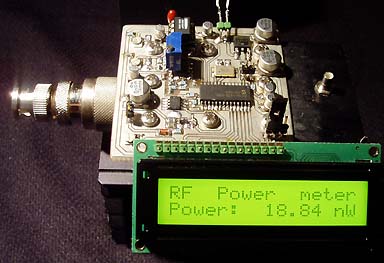
Since the Rin was 91.66 ohm we can calculate the scaling resistor of the ladder.
Scale = (Rladder + 91.66)/91.66 = > Rladder should be 4904 ohm.
In my case I use 1.5k + 1.5k + 1.8k + 100 = 4900 ohm....pretty good match.

Puhhhh, that was some bori...basic math, lets move on to more fun stuff :-)

The output signal from the AD8307 goes to an A/D circuit which are controlled by the PIC16F870.
To the PIC is an EEPROM connected. This EEPROM will contain the look-up table for the display.
The display in this project is a basic 2 line and 16 char LCD display based on a HD44780 controller circuit (most common).
As I told you earlier, the EEPROM must be programmed from a computer to make this unit work properly. The connection to a computer is done by a RS232 wire. The programming procedure is very simple: Start the main program in the computer and connect the RS232 wire to the wattmeter.
Before you turn on the power of the wattmeter you should make sure that the switch SW1 is closed.
This will indicate the PIC that it should program the EEPROM.
Now turn on the power and hit the button of the software called "Program EEPROM".
Everything will now be automatically. When program is finished you should turn off the power and remove SW1. The unit is now ready to be used.


Windows Software
This is the software to load the EEPROM. 
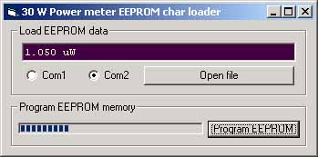
This is the Window software I use to load the EEPROM. The software is quit simple. Connect the wattmeter to the the computer via RS232-cable. Choose Com1 or Com2. Click Open file button and choose the file called "data.txt" which contains the pre calculated table.
When the EEPROM i loaded the wattmeter will go into normal mode and display the actual power.

The PIC and windows software is zipped (software + data.txt) and can be download by links below:

Download PIC16F870 program (INHX8M format)
30w_meter.zip PIC software (the hex files are zipped!)

Download software
Download windows software + data.txt (table)
XP Version 30w.zip (3.9Mb)
Click here to go to the software download page!


Final word
This project explain how you can build a very powerful wattmeter toll by using a simple circuit called AD8307.
I choose to make this wattmeter digital and the display showed the power in watts.
A good wattmeter is very important to have and I really advice you to build a wattmeter or some kind of measuring tool when you are working with RF and transmitters.
It will really make your work easier.
I wish you good luck with your projects and thanks for visit my page.


Back to main Page  |  Contact Me  |  Cheap components

Copyright © Last modified on 16 november 2005.