Click on the pic to see larger photo! 
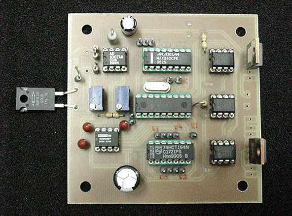
Digital Wattmeter for RF based on AD8307
This project will explain a digital wattmeter from 1pW to 10mW up to 500MHz.
The wattmeter can work alone or together with a computer for collecting data.
Information will be displayed in dBm, Watt, and Voltage into 50 ohm.
With proper attenuator, the measure range can go up to 1kW.
The unit is very accurate, fast and easy to build.

All contribution to this page are most welcome!

Background
What is the purpose of a wattmeter. In all your RF application you will have great advantage if you can measure the signal or the power. To measure the signal you will probably use an expensive oscilloscope or some other extremely expensive RF instrument. One major purpose for me to build this project is that I did fool myself for long time. I used a new HP 100MHz oscilloscope and I measured the amplitude over the 50 ohm dummy load. From the amplitude I then calculated the power. For month I was very dissapointed not to be able to generate more than 100mW output power. One day I burned up the dummy load totally.
How is this possible with 100mW?
I started to measure the temperature in the dummy load and then put DC into the dummy load. I increased the DC current until I reached the same temperature. What I noticed was that I had to put 3-5W into the dummy load to reach the same temp. The conclusion was simple to make: The oscilloscope should be run over by a truck or a tank! So I need a reliable Wattmeter.
What every homebrewer should have is a wattmeter. A wattmeter use a 50 ohm dummy load and will present to you the energy into this load. The most widely used reference in RF systems is decibels above 1 mW in 50 ohm, written dBm.
There is a circuit AD8307specially made for this purpose and it has a very wide working range and is very easy to use.

How you calculate power


Above you can see a AC generator and a resistor of 50 ohm. A current will flow in the circuit and you can easy calculate the effect which will be consumed by the resistor. The effect will be transformed into heat. In the blue frame you can see how I calculate the power to 20mW. The red frame show how you can calculate the power into dBm, which which stand for decibels above 1 mW in 50 ohm, written dBm.
In the green table at rigth I have calculated some power into PdBm.

Block diagram


The power is measured by the circuit AD8307 over a 50 ohm dummy load. An A/D converter of 12 bit convert the analog output from the AD8307 to a digital number. Since the AD is a12 bit A/D you will have 4096 combinations. The output values will be from 0 to 4095. To calculate the power into dBm you need some mathematical calculations. I have solved this in a more simpel way, since it is a bit difficult to implement mathematic into the PIC. I use a look up table. It is memory bank containing all the display text. I have pre-calculated all the display text for each A/D value. The output values from the AD (0 to 4095) points to a direction in the memory where the actual display text value is stored. The text will be fetched and presented on the display.

The advantage of using a memory map is that it will be easy to build, I can implement prefix in the text, It will be fast and it will work! In reality I will use 3 EEPROM of 32k. Totally I will use 98k. The EEPROM is cheap but there is one tricky thing to do. The memory table must be programmed into the EEPROM before it can be used.
It is very important to hand program each byte manually to get it working. *smiling*...just joking!
If you don't have a "manually programming unit" you can simply connect a RS232 cable to a computer and use the program I will support you with. This program will handle everything, just start the program and go make yourself a cup of coffee.
Every memory cell will take 10ms to burn so it will take 12-15min. Once the EEPROM has been programmed you will not have to do this again.

Memory table:
This is the content of the memory table. Below you can see some of the first A/D values and the last A/D values.
To the left you will see the A/D value and the rest of the line is the display text.
As you can see, for each A/D value you will have a line of display text.
First there is the sign then comes the power in dBm and then the power in Watt and last you will have the Voltage over the 50 ohm.
As you can see I have also added the prefix as milli, micro and nano which will give a nice displaying.

AD Sign PdB      W        V
-----------------------------------
4095 +  9,98 dBm 9,954 mW 705,5 mV
4094 +  9,95 dBm 9,886 mW 703,1 mV
4093 +  9,93 dBm 9,840 mW 701,4 mV
----
----
0003 - 89,93 dBm 1,016 pW 7,127 uV
0002 - 89,95 dBm 1,012 pW 7,113 uV
0001 - 89,98 dBm 1,005 pW 7,089 uV
0000 - 90,00 dBm 1,000 pW 7,071 uV

20dBm Attenuator


This is the attenuator you can use if you want to measure higher effects than +10dBm.
The input impedance is 50ohm and the output impedance is matched for 50 ohm which the wattmeter has as input impedance.
This attenuator will attenuate 20dBm (100 times).
If you use the attenuator and read +10dBm you will have to add 20 to it and the real effect will therefore be +30dBm.
If you want you can load the EEPROM with a table adjusted for the attenuator to show the true value.
You can read more about it below in the software section.

Schematic
Click on the pic to see a larger photo!

Here is the schematic. The AD8307 circuit measure the power and an A/D convert the analogue signal to the PIC. The PIC has 3 EEPROM to read the display text. The display is a standard 2 line 16 char LCD display.
To the PIC is also a RS232 interface for programming the EEPROM and to send the display text during measurement. A swith SW1 must be pushed to program the EEPROM. When this button is pressed the wattmeter communicate with the windows software and program the display table.
Rmember, you only need to program the wattmeter one time!

Windows Software


Download software
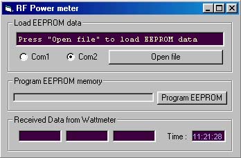
Download windows software
wattmeter.zip (2.03Mb)
Click here to go to the software download page!

This is the Window software I use to load the EEPROM. The software is quit simple. Connect the wattmeter to the the computer via RS232-cable. Choose Com1 or Com2. Click Open file button and choose which table to load into the EEPROM. There is two table (see below).
One table wattm_1.zip is used when there is no attenuator connected to the wattmeter. The measure range will be -70dBm to +10dBm.
If you use the 20 dBm attenuator you have to add 20dBm to the displayed values OR you can load the EEPROM with a table made for the attenuator.
If you load the wattmeter with the table wattm_2.zip and you use the 20dBm attenuator you will read the exact value on the display.
The range will now be from -50dBm to +30dBm.
If you want you can use two attenuators in serie. You will then attenuate with 40dBm. I do not have any table for this,
so you will have to add 40 to the display value.
When the EEPROM i loaded the wattmeter will go into normal mode and display the actual power. You will also see the info in the
Received Data from Watteter windows at the bottom of the windows.
Make sure you don't overload the wattmeter!

RS232 communication
The interface works at 19200 baud, 1 startbit, even parity and 1 stopbit (19200,e,8,1).
The table at right show you an example of the 18 byte that the wattmeter send at each measurement.

  • Char 1 - 6 is the power in dBm.
  • Char 7 - 12 is the power in watt in the 50 ohm.
  • Char 13 - 18 is the voltage over the 50 ohm.


  • Download EEPROM display text
    wattm_1.zip Display text for -70dB to +10 dBm, the file is zipped!)
    wattm_2.zip Display text for -50dB to +30 dBm, the file is zipped!)


    Download PIC16F84 program (INHX8M format)
    wattm.zip PIC program wattmeter

    Download some datasheets
    AD8307.pdf Datasheets for AD8307.pdf

    Final word
    I hope you will enjoy this powermeter-project.
    I also hope I have given you some new ideas and knowledge.
    You can always mail me if there is anything unclear.

    I wish you good luck with your projects and thanks for visit my page.
    If some cases I can help you with the support of components to this project.


    Back to main Page  |  Contact Me  |  Cheap components

    Copyright © Last modified 1 June 2003.