 The computer control (set) the receiving frequency from 45-860MHz
On this page you will find all these parts and you will also be able to download the softwares for the project.
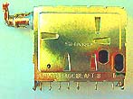
So go out and hunt for an old UV916 or UV918 tuner.
RS232 to I2C converter from the computer to the tuner
I2C use 2 wires. One is the SCL (clock line) and the other is the SDA (data line). A data transfer consist of a 7 bits and a read/write bit. When the master (In my case the PIC16F84) clocks 8 data bit the slave (In my case the tuner) answer with an acknowledge bit. I am not going to explain more how I2C works, you can find more info about it on the internet.
The figure below shows a transmission of one byte over I2C.
The schematic below shows the interface between the computer and the tuner.
Inside the tuner (If you open the cover) you will find a circuit TSA5512 wich is the I2C controlled PLL synthesizer in the tuner.
The PIC16F84 is common used microcontroller. You can find programer and software for this processor all over internet.
On my meny page you find some software for this processor.
The output from the COM Port of the computer has RS232 standard. The voltage swings between +/- 12V. A circuit MAX232 converts the signal to 0/+5 Volt wich is the level the PIC can handle. Pin 17 and 18 on the PIC are used for the communication to the computer. The pin 12 is the SCL and the pin 11 is the SDA wich both are connected to the tuner.
A simple testing to make sure the converter works:
Connect a oscilloscope or little speaker or piezo -summer at pin 13 on MAX 232. When the computer send the 5 byte on the RS232 port (COM Port) you will see the signal or hear a clicking sound in the speaker. At pin 12 on MAX232 you will have the same signal but the voltage level will be 0 to +5V instead.Now, check at pin11 and 12 on the PIC. When all the 5 byte are transmitted you will find a I2C data transmission (also clicking sound).
It is important that the crystal at the PIC is 4.000MHz, because it controls the baud-rate.
There is a LED in the schematic at pin 13. This LED will start to light when the first of the five bytes is received. It will turn of when the last byte is received. The HEX-fil for the PIC (software) can be found at the bottom of the page!
I some cases I can assist with the programming of this circuit.
The five internal registers in the tuner
I will explain in more detail about the data wich is transfered from the computer to the tuner.
The tuner has 5 register. You can find them in the datasheets (TSA5512) or in the table below.
The Windows Tuner program I have made, handles all the setting of the five registers.
| Event |
|||||||||||
| Address | |||||||||||
| Programmable divider |
|||||||||||
| Programmable divider |
|||||||||||
| Charge-pump and test bits |
|||||||||||
| Output ports control bits |
MA1,MAO = 0 ,1 => Tuner always valid
N14 - N0 = Programmable divider
Example: N14-N0 = 1600 (decimalt) then the tuner oscillator will be 8 * 7812.5 * 1600 = 100MHz
CP = 0 Chargepump = 50uA fine tuning
CP = 1 Chargepump = 220uA fast tuning
T1, T0, OS = 0 0 0 =>Normal operation
P7-P0 sets the desired frequency band
The adress activates the tuner. By applying different voltage to P3 (Input pin on the tuner) at the tuner different adresses can be selected. By selecting MA1=0 and MA0 =1 the tuner is always valid indipendent of the voltage at P3 (I let it flow)
The divider register set the frequency in the tuner. If you multiply the content of this register with 62500 you will end up with the frequency the tuner will be locked at.
The charge pump register and testbits controls the tuning speed and some test performance can be made.
See datasheets for more info.
Output ports control bits select the desired band. There are three bands
LOW BAND 45-180MHz = $A0
MID BAND 160-470MHz = $90
HIGH BAND 430-860MHz = $30
If you want to set the register by yourself and maybe make your own programs you must send the 5 control bytes to the PIC via RS232.
The baudrate should be 19200,e,8,1
FM receiver for the 38.9MHz
What the tuner does is to mix the RF from the input antenna with a internal osc (the frequency you have programmed in the register).
The output product IF-signal from the tuner is 38.9MHz. The external FM-receiver will be set to receive at 38.9MHz always.
Example: Lets say the tuner oscillator is programmed to 144MHz.
We know the external receiver will always receive at 38.9MHz, therefore the RF frequency I will receive will be: 144MHz-38.9MHz =105.1MHz.
You can also think like this : The RF-frequency I want to listen to is = the tuner programmed frequency minus 38.9MHz.
In my program you will see tree windows. The first window shows the tuner oscillator frequency. The next window shows the IF frequency ( the frequency the external radio receiver is set to). The last windows show the receiving frequency.
The schematic below show the complete harware of the tuner and the radio receiver for 38.9MHz.
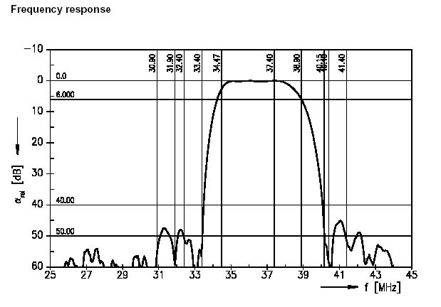 The IF signal from the tuner is filtered in a SAW-filter befor it comes to the receiving chip. The SAW- filter is specially made
for TV and VCR:s. This filter is a ceramic filter and it is a sharp passband filter for 34.47MHz to 38.9MHz.
The IF signal from the tuner is filtered in a SAW-filter befor it comes to the receiving chip. The SAW- filter is specially made
for TV and VCR:s. This filter is a ceramic filter and it is a sharp passband filter for 34.47MHz to 38.9MHz. It supress all other frequency well.
If you follow the IF-output from the tuner at the circuitboard in a TV you will come to the SAW filter.
Read more about SAW filter here!
The FM-receiver is based on the circuit MC13136. The LO oscillator is tuned by a inductor and a capacitor at pin 1 to 49.6MHz.
This circuit has 2 mixers one is the LO and the other is crystall controlled at 10.245 MHz.
The IF in MC13136 is 10.7 MHz and therefore the receiving frequency will be 49.6 -10.7 = 38.9 MHz.
You can verify the frequency by connection a frequency counter to pin 3 wich is a buffered LO output, and adjust C1 until you reach 49.6MHz. Two ceramic filters 10.7 MHz and 455kHz filter the IF and a quad-coil demodulate the audio. This circuit is not difficult to build and adjust. See datasheets at bottom or more info.
The audio level output from this circuit is 50-200mV so you need an amplifier to hear the audio.
At pin 16 you will find the RSSI signal(signal strength indicator).
Window software to control the tuner
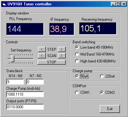 I have made a simple Windows program to control the tuner. The program set the 5 register. The program display 3 windows.
The window at left shows the programmed frequency (VCO). The second window show the IF frequency. In my case it is 38.9MHz.
You can edit this window and set different value. Remeber you should be between 34.47MHz to 38.9MHz to get the best performance
from the SAW filter.
I have made a simple Windows program to control the tuner. The program set the 5 register. The program display 3 windows.
The window at left shows the programmed frequency (VCO). The second window show the IF frequency. In my case it is 38.9MHz.
You can edit this window and set different value. Remeber you should be between 34.47MHz to 38.9MHz to get the best performance
from the SAW filter.The last window will show you the frequency you are listening to, the true frequency.
The first thing you should do when you run the program is to set wich comport you are using.
Testing:
A simple way to test that the tuner works is to monitor the tuning voltage by applying a voltmeter to the R1 resistor (Utuning), see schematic.
The voltage here should increase when you are increasing the frequency. In the begining of every band the voltage is close to 0 volt and at the end of each band the voltage should be close to 25-33Volt.
Download
| SAW filter.pdf | SAW filter datasheet |
| TSA5512.pdf | 1.3 GHz Bidirectional I2C-bus controlled synthesizer |
| MC13136.pdf | FM Receiving circuit |
| UV916hex.zip | HEX-code for the PIC16F84 (INHX8M format) The file is zipped! |
| uv916_2007.zip | Latest Version! HEX-code for the PIC16F84A (INHX8M format) The file is zipped! The LED will blink 3 times on power up to show OK status. This LED will also start to light when the first of the five bytes is received. It will turn of when the last byte is received. |
Download windows software uv916.zip (2.42Mb) |
|
Click here to go to the software download page! |
|