This photo show the PCB backside of the frequency counter. The LCD display is placed on the front side. Very small unit and still so powerful. 
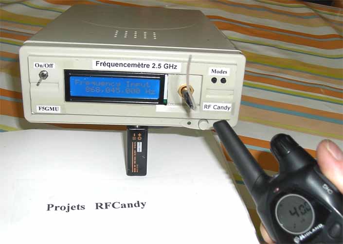
Exclusive 2.5 GHz Frequency Counter
with Blue 2x16 LCD display

This project explain a very powerful frequency counter which has many useful software functions.
The software can add or subtract 3 different IF frequencies (±455 kHz ,±10.7 MHz and ±21.4 MHz).
You have also two level of resolutions, 1kHz and 100Hz.
The main oscillator can be on-board 13MHz or external 10 MHz.
The counter data can easy be transmitted to computer with RS232 cable (software below)
The construction is extremely simple and the unit is very small.
This project comes in a KIT version, se more details below.
All contribution to this page are most welcome!

Background
Once again, It is time to update the frequency counter.
A frequency counter is one of the most important measuring tool we need as homebrew's of RF electronic.
This frequency counter has very high performance and still is very easy to build and to use.
Anyone can build it and have a professional frequency measuring tool.
The counter is based around a LCD display with 2 lines and 16 chars.
I have used a HD44780 based display which is very common.
A PIC16F870 circuit controls all counting and display functions.
A prescaler is added to make it possible to measure up to 2.5GHz with high sensitivity.

The Display Module Size (W x H x T): 80mm X 36mm.
The controller PCB has the same size. This makes the unit very small and slim.

Click on the picture to see the full PCB. Very easy to solder. In the menu system of this frequency counter, you can choose between two reference frequencies.
  • On-board 13.000MHz crystal (picture at right), or
  • External 10.000MHz signal.
    The reason of using a external 10.000 MHz reference frequency is because it is common among reference oscillators, as HP Z3801 GPS locked frequency source.


  • What is the reason to add/subtract the IF frequency ?
    Radio receivers today works with an intermediate frequency (IF). There is three frequencies which are often used and they are 455 kHz, 10.7MHz and 21.4MHz. The reason of having a intermediate frequency is to optimise the filtering in a receiver. The picture at right show you the basic principle of a receiver. You have an antenna connected to a mixer and a LC unit (oscillator) which also is connected to same mixer. The product of the mixer will be many different frequencies, but the most interesting are the IF at 10.7 MHz or 455 kHz.
    To produce the IF frequency, your oscillator must be running 10.7 MHz above the desired frequency or 10.7 MHz below the desired frequency.
    Same if the IF is 455 kHz, then the oscillator must be running 455 kHz above the desired frequency or 455 kHz below the desired frequency.
    Example:
    You want to receive at 100 MHz. Then the OSC is set 110.7 MHz and that will give you and IF of = 10.7 MHz.
    If you now measure the OSC your frequency counter will show 110.7 MHz, but you are listening to 100 MHz!!!
    What we want is to (add) or subtract the IF (10.7 MHz) from the measured frequency so you can se the actual receiving frequency.
    The software in this counter can handle all that for you. Just hook up the counter with your receiving OSC and enjoy.
    Detailed information about receiver IF and OSC can be found by clicking this link.
    Click here to view a larger schematic
    Hardware and schematic
    The main part of this project is a LCD, PIC16F870 and a prescaler LMX2322.
    The LCD is a standard 2 line 16 chars display connected in 4-wire mode to the PIC.
    At the bottom you will find a 13.000 MHz or external 10.000 MHz frequency connected to the PIC.
    Capacitor C9 is variable and is used to calibrate the Frequency counter.
    If you have an external 10 MHz oscillator you should remove the crystal, C8, C9 and connect the signal to pin 9 of the PIC16F870.
    At pin 5 you have an output. It can be connected to a piezo buzzer or equal to generate a beep whenever any button is pressed.
    If you don+'t want to use it, you can leave this pin as it is.
    Pin 2 is the switch SW1 which you can toggle choices in the menu system.
    Pin 4 is the switch SW2 which guide you through a seven stages menu system.

    PCB and KIT
  • Below you can find all info to make your own PCB for this counter.

  • If you wish to buy a complete KIT with a factory made PCB, you can go down to section named "KIT" a bit down. Click here to jump down!


  • Click on rhe picture to enlarge.
    freq232.pdf PCB file for Frequency Counter LCD (pdf).

    Above you can download a (pdf) filer which is the black PCB.
    The PCB is mirrored because the printed side should be faced down the board during UV exposure.
    To the right you will find a pic showing the assembly of all components on the same board.
    This is how the real board should look when you are going to solder the components.
    It is a board made for surface mounted components, so the copper is on the top layer.

    Grey area is copper and each component is draw in different colours all to make it easy to identify for you.
    The scale of the pdf is 1:1 and the picture at right is magnified with 4 times.
    Click on the picture to enlarge it. Slim construction

    Assembly
    Good grounding is very important in a RF system. I use bottom layer as Ground and I connect it with the top layer at three places (via-holes) to get a good grounding.
    Drill a small hole through the PCB and solder a wire in each via-hole to connect the top layer with the bottom layer which is the ground layer. The three via-holes can easy be found on the PCB and in the assembly pic at right, they are labelled "GND" and marked with red colour. Drill the remaining 16 holes for the Pin Header 2.54mm which will connect the LCD to the PCB.
    Since the back plane of the PCB is Ground you must make sure there is no connecting copper to the Pin Header 2.54mm at the backside. Easiest way is to remove the copper at the backside is to use a larger drill (3mm) and drill a bit in the holes at the backside of the PCB.

    Soldering and testing:
    The soldering of this unit is pretty basic.
    Connect the LCD to the PCB with the (Pin Header 2.54mm).
    The PIC16F870 is soldered directly to the component side as if it was a smd part, (see picture at top of the page).
    I advice you to solder all components except the LMX2322.
    Connect power and make sure you got stable + 5V at the power line of the PIC16F870 and display.
    P1 will need to be adjusted to give good contrast of the display. The voltage at pin 3 of the LCD should be about 0.5V-1.5V.
    If everything is OK you should be in menu 1 "Frequency input"
    Since you have no input signal from any LMX2322, the reading will be zero.
    A jumper J1 is added to choose if you want strong backlight or not.
    If jumper J1 is disconnected the LCD will have soft backlight because a low current will pass through R6.
    If jumper J1 is connected you will have strong backlight.

    Calibration:
    When a 13 MHz crystal is used, the calibration of the counter is made by the variable capacitor C9. It will be able to change the timing ±100ppm (±10kHz at 100MHz). Most people has no good reference to calibrate against and then it is a bit difficult. The frequency counter is supposed to be a measuring tool with good accuracy.

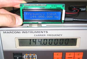
    One thing you can do is a "poor man calibration". You can use a good TCXO or equal with good frequency tolerance.
    I do have tested VCTCXO 12.800 MHz Crystal Oscillators manufactured by NDK (NKG3001B) which I have on my component page and it has ±2.5 ppm tolerance. I connect the 12.8 MHz ±2.5 ppm to the input pin 11 (RC0) of the PIC. Since I feed the input with 12.8MHz, I simulate an input RF signal of 1,638,400,000 Hz.
    The display should show now show 1,638,400,000 Hz. All you need to do is to tune C9 until you reach that on the display. Now you have frequency counter where the accuracy is ±2.5ppm (±250Hz at 100MHz).
    You can also use a Calibrated TCXO 10.000 MHz ± 0.1 ppm, See Shop then Tab Crystal -> TCXO
    A 10 MHz input signal should show 1.28 GHz (Same schematic at right)
    You can also use the 10 MHz reference crystal to drive the Counter.(See below)


    External 10 MHz reference system

    This counter can be run with two reference frequencies.

  • On-board 13MHz reference

  • External 10 MHz reference


  • Some small modification is needed for the external 10MHz reference.
    The external 10 MHz reference should be feed to pin 9 at PIC16F870.
    Remove (red marked) capacitor C9, crystal X1 and capacitor C8.
    Feed the external 10 MHz signal to pin 9, which you can find at crystal position, (see figure at right).

    The bottom pad of capacitor C8 is connected to ground and the bottom pad of J4
    is connected to Vcc (which can be used to drive the 10 MHz TCXO).


    How to connect a 10.000 MHz ± 0.1 ppm TCXO as reference
    Schematic at right show how you can connect a Calibrated TCXO 10.000 MHz ± 0.1 ppm
    to the Exclusive counter. Vcc and GND can be found on the PCB as figure shows.


    No pre- or post-flank errors!
    This frequency counter use intelligent gating system and special designed algorithm to detect eventual pre or post-flanks in the counter system.

    The result of this, gives a very accurate and stable frequency counter
    which you will only find in expensive commercial frequency counters.


    Soldering the LMX2322
    Here comes the big challenge.
    The desoldering wick is a flattened, braided copper sheath	
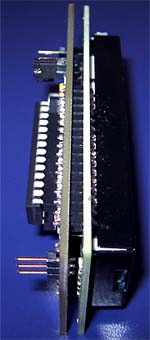
Click here to see photo and read how to solder SOIC and smd components.
    The circuit is a fine pitch SO-IC circuit and this little bug can make your life miserable.
    Don't worry I will explain how to handle it. Use thin lead solder and a clean soldering tool.
    I start by fixate one leg on each side of the circuit and makes sure it is correct placed.
    Then I solder all other legs and I don't care if there will be any lead bridges.
    After that it is time to clean up and for that I use a "wick".
    The desoldering wick is a flattened, braided copper sheath looking for all the world like shielding on phono cord (except that the shielding is tinned) without the cord.
    I impregnate the wick with some rosin and place it over the legs and bridges of the circuit. The wick is then heated by the soldering iron, and the molten solder flows up the braid by capillary action. After that, all bridges will be gone and the circuit looks perfect.
    Wick and thin soldering lead will be added in the KIT.

    Purpose of resistor R5
    Before you solder R5 you should test the frequency counter.
    The input of the LMX2322 (prescaler) is very sensitive. When the input is not connected to any source, the circuit will pick up any RF noise and start to self oscillate.
    This behaviour can be used to test the circuit function in a simple way. When the power is on, the display should show something like 1.4-1.6 GHz.
    If so, you can be sure that the PLL is soldered correctly and working fine. To prevent self oscillation, R5 is added to the input stage.
    This will make the counter show 0 when no RF signal is applied. R5 will not affect RF signal or sensitivity of the frequency counter.

    PIC Software
    Front side of the frequency counter 
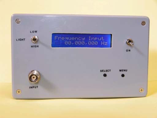
Let's have a look of the different menu systems and choices of this frequency counter.
    All settings are made by the two switches SW1 and SW2.
    The unit will always remember the last settings even if power is switched off.
    Figure below show all the different menu choices.

    SW2 will step you through a menu of seven choices.
  • Menu 1 will give the actual frequency.

  • Menu 2 will add 455 kHz to the frequency.

  • Menu 3 will subtract 455 kHz to the frequency.

  • Menu 4 will add 10.7 MHz to the frequency.

  • Menu 5 will subtract 10.7 MHz to the frequency.

  • Menu 6 will add 21.4 MHz to the frequency.

  • Menu 7 will subtract 21.4 MHz to the frequency.

  • Menu 8 will set the PIC16F870 reference frequency. (You can choose between On-board 13MHz or External 10 MHz).

  • Menu 9 will set the gate time. (You can choose fast 1kHz resolution or slow 100Hz resolution).


  • SW1 will toggle choices for you in menu 8 and 9.


    Custom made IF frequency
    If you wish to have other IF frequency option, please mail me.

    Windows software
    The software is FREE and you can change the skin as you wish.

    Download windows software & Source code

    The windows software is pretty simple. First you choose the input com port.
    I have extended it to 4 because lap tops (using USB to RS232 converter) often get com port 3 or 4. After choosing comport you simply press start.
    If you wish to, you can change the display colour by pressing "Display colour" button and choose other skin. You can of course make your own skin, as long as the gif picture (included files) has the same size as the examples. The picture above show some of them.
    The windows software and the VB code is free to use. If you are skilful programmer (which I am not) I will be happy to place your software here.

    Transfer protocol:
    The communication between the frequency counter and the computer is based on standard serial communication.
    The serial RS232 link use 1200 baud, 8 bit, no parity and one stop bit (1200,n,8,1).
    The transfer protocol is very simple. Each package of data consist always of 8 chars.

    Example: The counter measure 1,020,157,000 Hz (as picture above)
    The 8 transmitted chars will be "10201570". (8 chars)
    Since the lowest resolution is 100 Hz, the last two zero's are not transmitted by the counter, they are added in the windows program.
    If the frequency is less than 1GHz or less than 100MHz the first two chars will be "space" to generate the 8 transmitted chars.

    Sensitivity of input signal
    Table below show my measurements of the sensitivity of this unit.
    This counter will work best when the input frequency is from 5.0 MHz to 2.5 GHz.
    Below you will see a table of some measurement I have made with a Marconi Signal Generator 2019A.
    I have also measured VCO:s at 2.0 -2.5 GHz perfectly.
    The input signal is terminated at the prescaler with 100 ohm and since the input impedance of the prescaler is 100 ohm you have a total input impedance of 50 ohm.

    Marconi Signal generator 2019A
    Frequency (MHz)
    mV rms
    uW (into 50 ohm)
    dBm (into 50 ohm)
    5.0
    280
    1600
    +2.0
    10.0
    126
    316
    -5.0
    50.0
    40
    31
    -15
    100
    22
    10
    -20
    200
    11
    2.5
    -26
    300
    8.9
    1.6
    -28
    400
    7.1
    1.0
    -30
    500
    7.1
    1.0
    -30
    600
    7.1
    1.0
    -30
    700
    7.1
    1.0
    -30
    800
    7.1
    1.0
    -30
    900
    7.1
    1.0
    -30
    1000
    7.1
    1.0
    -30

    Attenuator
    Sometimes your RF signal is to strong for the frequency counter and then you can add attenuators between the signal source and the frequency counter.
    An attenuator is an electronic device that reduces the amplitude or power of a signal without appreciably distorting its waveform.
    Attenuation are expressed in decibels of relative power.
    As a rule of thumb 3dB pad halves power, 6dB quarters, 10dB is tenth, 20dB is 100th, 30dB one in one thousend and so on.
    For voltage you double the dBs so for example 6dB is half in voltage.

    Attenuators are very simple to build, and they works really good.
    The picture at right show you how to build a 6dB attenuator.
    You can serial connect several attenuators if you need to.

    6dB means that the output power is only 1/4 of the input power.
    It also means that the output voltage is 1/2 of the input voltage.
    As you see I have used 100 ohm SMD resistor because they are cheap, purely resistive and also accurate.
    Here is a good and simple link for calculate attenuators: Pi & Tee Network Resistive Attenuation Calculator


    KIT
    This project is a must for all homebrewers, so therefore I have put together a complete kit with a factory made PCB.
    All components, PCB, LCD, and PIC16F870 for Exlusive 2.5GHz Frequency Counter are included in the KIT (Click here to download component list.txt).
    If you only want to buy a pre-programmed PIC16F870, Click here and look under ICs -> MCU Pre-prog.

    Order a KIT
    which will include all parts listed below
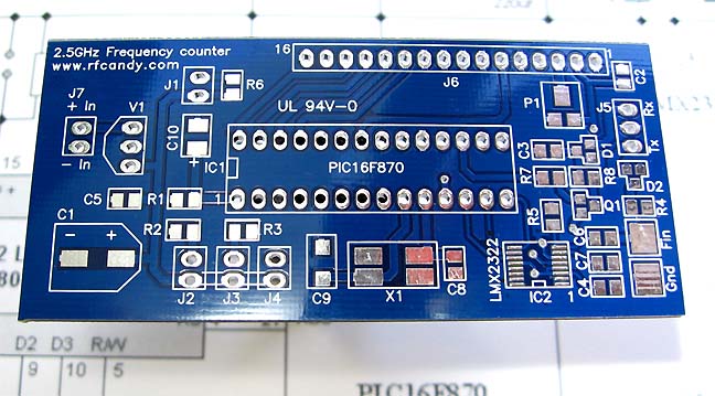
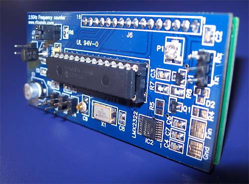
    Factory produced PCB

    Click on the picture to see larger
    Click on the picture to see larger photo.
    The PCB is blue and factory made.
    1 pcs
  • Blue PCB factory produced - See photo at right
  • 1 pcs
  • 16x2 LCD w/ HD44780 Controller & Blue Backlight
  • 1 pcs
  • PIC16F870 PIC16F870 pre-programmed with software (DIP)
  • 1 pcs
  • 28 pin IC socket for PIC16F870 (DIP)
  • 1 pcs
  • Prescaler circuit LMX2322 smd
  • 1 pcs
  • BC856 (PNP Q1) smd
  • 2 pcs
  • MMBD7000LT1-D (Diode D1, D2) smd
  • 1 pcs
  • Crystal 13.000MHz smd high performance (X1)
  • 1 pcs
  • 78L05 + 5 VOLT REGULATOR (V1)
  • 1 pcs
  • 22pF smd (C8)
  • 1 pcs
  • Variable capacitor smd (C9)
  • 2 pcs
  • 1nF smd (C6, C7)
  • 4 pcs
  • 100nF smd (C2, C3, C5)
  • 1 pcs
  • 2.2uF smd (C10)
  • Download assembly maual

    Click on the picture to see larger
    Click on the picture or on pdf to download.
    freqmanual.pdf
    1 pcs
  • 47uF smd (C1)
  • 2 pcs
  • Resistors 100 ohm smd (R4, R6)
  • 1 pcs
  • Variable resistor smd (P1)
  • 5 pcs
  • Resistors 3.3k smd (R1, R2, R3, R7, R8)
  • 1 pcs
  • Resistors 100k ohm smd (R5)
  • 1 pcs
  • 16 pin header (J6)
  • 1 pcs
  • 3 pin header (J5)
  • 5 pcs
  • 2 pin header (J1, J2, J3, J4, J7)
  • 1 pcs
  • Jumper (J1)
  • 1 pcs
  • soldering lead (Extra thin)
  • 1 pcs
  • Cleaning wick (to clean up bad soldering)

  • Order here

    Features
  • Frequency range from 5 MHz to 2.5GHz
  • 16 character by 2 line high contrast LCD
  • 10 digit frequency display
  • Programmable IF offset
  • 2 pushbuttons for user programming
  • On-board oscillator 13MHz or external 10 MHz
  • RS232 communication to computer
  • ESD protected input
  • Small dimension 1.5" x 3.1" (37 mm x 80 mm)
  • Easy to build (one evening project)

  • Trouble Shooting section
    If you get a problem with your unit, you might find this section helpful.

  • I get no text on my display!

  • Make sure you have +5V to pin 2 of the LCD and that the background light is working.
    You should now test that the contrast voltage of the LCD is ok.
    The voltage at pin 3 of the LCD should be about 0.70V to 1.5V
    This will give good contrast!
    You should also make sure you have 5, 7, 8, 9, 10 to ground.
    Now, you should test that the data signals is arriving to the LCD.
    Look at the signal of pin 14, 13, 12, 11, 6 and 4 and make sure you measure on the LCD.
    I often use a small speaker or piezo element and listen to the signals.
    You should hear clicking sound or beeping tone…
    If you don't have any data communication to the LCD the problem is with the PIC16F870, next section.

  • My PIC16F870 is not working!

  • Make sure you have +5V to pin 20 of the PIC.
    You should test that the Reset (pin 1) goes high when power is turned on.
    The oscillator should be running at 13MHz. (Test with oscilloscope or equal equipment)
    Make sure that RA0 (pin 2) and RA2 (pin 4) is low and goes high when SW1 or SW2 is pressed.

  • The LCD show only zero so my LMX2322 is not working!

  • Check that the circuit is placed in correct way.
    Check that you do not have any soldering bridges between legs or to ground.

  • My RS232 computer communication is not working!

  • Make sure you that you have a RS232 digital signal out on RC6 (pin 17).
    Transistor Q1 with D1 generate a level shift to +5V and -12V for communication to computer.
    At the collector of Q1 you should have the RS232 signal jumping between -12V and +5V.
    (This will only work when the unit is connected to a computer since the -12V comes from the computer.)
    If you do not have this, make sure you have connected the TX, RX, and ground on the D-sub correct.

    Any com-port program (terminal software) can be used to test that data enters the comport of the computer.

    Final word
    In this part, I describes a very powerful frequency counter with high sensitivity and smart software functions.
    Beside all that, it looks pretty cool.

    Building manual
    A customer Mr Lars A, has sent me a very professional step-by-step PDF-manual,
    where he describes how he built his frequency unit and what he bumped into during the assembly.
    Great work Lars, and we all thanks you for your effort.

    Download PDF manual
    Building the Frequency Counter.pdf (760kb)
    Click here to download file

    Photo Gallery
    Some assembled counters people has mailed me. Please mail me more.

    Geert from Nederland sent me this nice photo. Great work! Click the pic to see larger photo Piet from Nederland sent me this nice photo and explained how he made a test. Great work! Click the pic to see larger photo. 
-A test while transmitting with a porto next to the unit. 
Its working very good, locks at the right frequency at once, with on input connection with 100nf capacitor connected to ground,and the other end to a little antenna connected to a bnc at the case. Jorge from Portugal sent me this nice photo. Great work! Click the pic to see larger photo! Bo from Denmark sent me this nice photo. Great work!    Click the pic to see larger photo!
- Bo writes that he tested his amateur radio at 145.400MHz, and he connected a small antenna to the counter. The function was perfect! Gérard from France sent me this nice photo. Great work!    Click the pic to see larger photo!
- Gérard has a custom made frequency unit where the IF frequency can be set to ± 37.30MHz Giacomo from Italy sent me this nice photo. Great work!    Click the pic to see larger photo!
-Giacomo write: mission over! Just one hour to sold and test. All very well.
With high signal, lower frequence appare about 10-15 MHz. Of course it is a VHF/UHF counter.
Sensibility at  about 500 MhZ is very very good. Kypros from Cyprus sent me this nice photo. Great work!    Click the pic to see larger photo! Kypros writes:
- As I promised I am sending you some pictures of the finished 2.5 Ghz frequency counter that I bought as a kit from you. 
It is a very nice piece of equipment and thank you for this and the effort you made to design it.
Jerome from Canada sent me this nice photo. Great work!    Click the pic to see larger photo! 
Vladislav from Russia sent me this nice photo. Great work!    Click the pic to see larger photo! 
Fernando from Brazil used a pre-programmed PIC and made the PCB and found all the parts himself. Fernando sent me this nice photo. Great work!    Click the pic to see larger photo! 
André from The Netherlands sent me his construction. Great work!    Click the pic to see larger photo! 
Piet constructions. I am impressed!    Click the pic to see larger photo! 
Mr Jean Yves from France sent me this photo of his Frequency counter. Here he test it with his 868.045MHz transmitter, and use a wire as input antenna to pick up RF. Great work! Click the pic to see larger photo Mr Luc from The Netherlands sent me this photo of his Frequency counter unit. 
He also has a gps-time base (10Mhz)build-in. Great work! Click the pic to see larger photo Mr Lars from Denmark sent me this photo of his Frequency counter unit. 
-The kit was easy to build and works excellent!  Great work Lars, and thanks for showing your unit


    Back to main Page  |  Contact Me  |  Cheap components

    Copyright © Last modified on 26 Sept 2006.