 Transcendent Frequency Counter
 Each channel has been designed to deliver maximum performance and high sensitivity.
The reason of using an external 10.000 MHz reference frequency, is because it is common among reference oscillators, as rubidium oscillators or HP Z3801 GPS locked frequency source.
The Transcendent frequency counter has been tested with a GPS reference with the accuracy of 0.1 e-12 (1 Hz error at 10000 GHz). The Transcendent worked perfectly.
The picture at right show my own 10.000 MHz Atom ref oscillator, based on the well known Efratom Rubidium LPRO-101.
It takes 2-3 minutes for it to lock, and the accuracy is then 0.5 e-9 (0.5 Hz error at 1 GHz).
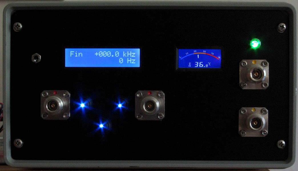
I have a RGB-LED at top right corner that starts to blink green when the unit is locked. (Red when unlocked.)
After 20 minutes the efratom is stable in temperature and the LED gives a constant light. The accuracy is then 2 e-11 (2 Hz error at 100 GHz).
To the left you can see my Transcendent counter with the two input connectors. I have three buttons with integrated blue LEDs, to control the menu.
With this little unit, I have both a 10.000 MHz output reference signal and a frequency counter, which use the 10 MHz reference for accurate measurement.
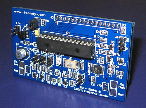
 A jumper J1 is added to choose if you want strong backlight or not. If jumper J1 is connected you will have strong backlight.
 Assembly

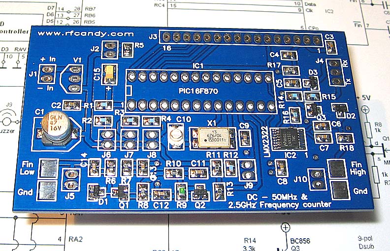
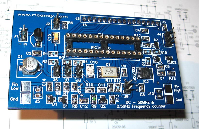
 Power to socket
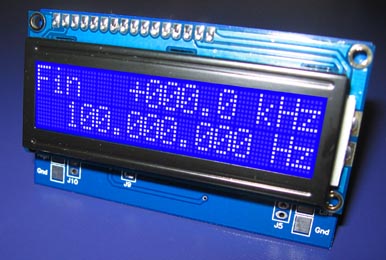 PIC Software