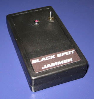
 The Black Spot - GPS Jammer with 3.4W EQP
 An upcoming range of devices are GPS trackers as GPS Vehicle Tracking and Person Monitoring Tracking.
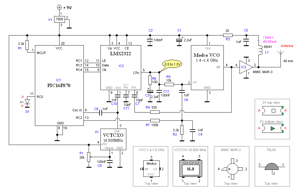
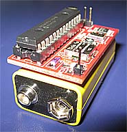 Hardware and schematic
 Assembly
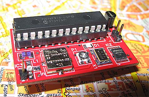
|
Mount X1
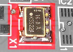 Solder as picture show. |
Mount VCO
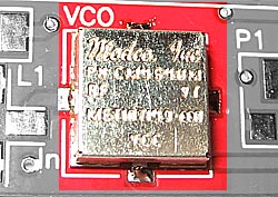 Try to center VCO in as good as possible. |
Mount P1
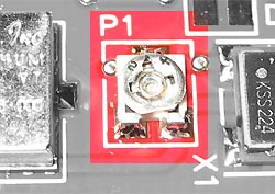 Solder as picture show. |
|
IC2 LMX2322
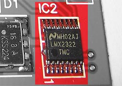 Solder as picture show. |
IC3 MMIC MAR-3
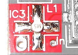 The leg with 45 degree cut, is the input. Note the text M5 is up side down. |
L1 inductor
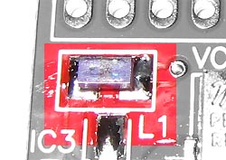 Solder as picture show. |
|
D1 Led
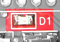 Green Marking to the right. |
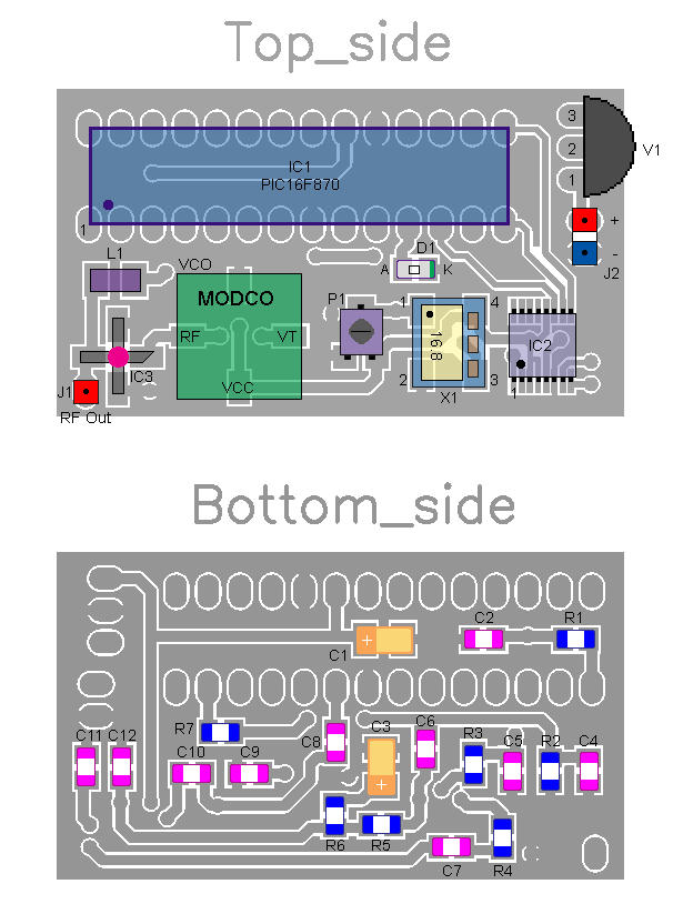
Mount 28 pin IC socket for PIC16F870, V1, J1 and J2
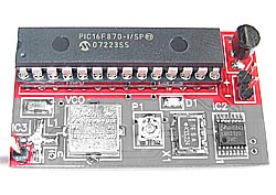 Solder the hole mounted parts as picture show. |
C1, C2, C3, C4, C5, C6, C7, C8, C9, C10, C11, C12, R1, R2, R3, R4, R5, R6 and R7
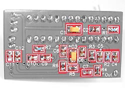 Solder the smd mounted parts as picture show. |
| s_gpsjam.zip | GPS software (the hex file is zipped!). |
| jammer.avi | download video (4.5 Meg). |
 Order a KIT
which will include all parts listed below |
Factory produced PCB
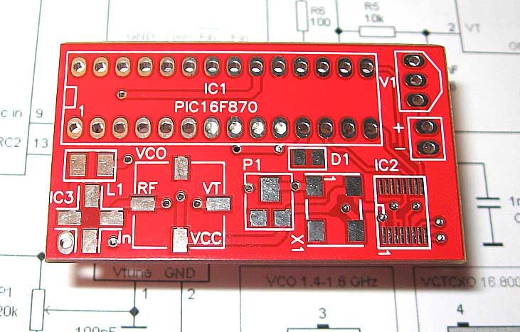 Click on the picture to see larger photo. The PCB is blue and factory made. |
|||
|
1 pcs
|
|
|||
|
1 pcs
|
|
|||
|
1 pcs
|
|
|||
|
1 pcs
|
|
|||
|
1 pcs
|
|
|||
|
1 pcs
|
|
|||
|
1 pcs
|
|
|||
|
1 pcs
|
|
|||
|
1 pcs
|
|
|||
|
1 pcs
|
|
|||
|
5 pcs
|
|
|||
|
3 pcs
|
|
|||
|
2 pcs
|
|
|||
|
1 pcs
|
|
|||
|
1 pcs
|
|
|||
|
1 pcs
|
|
|||
|
2 pcs
|
|
|||
|
1 pcs
|
|
|||
|
1 pcs
|
|
|||
|
1 pcs
|
|
|||
|
1 pcs
|
|
|||
|
1 pcs
|
|
|||
|
1 pcs
|
|
|||
|
1 pcs
|
|
|||
|
1 pcs
|
|
|||
|
Order here |
Features
|
|||