Klick on the pic to zoom! 50MHz Transmitter for the IR detector
This project is about an IR-detector (Infra Red) combined with a 100mW 50MHz transmitter.
The detector is sensitive to changes in IR-spectrum and is commonly used in burglar alarms.
When the detector sens a person/animal/ghost/angry clown, it will transmitt a warning signal
to a portable receiver and you will get a pre-warning.
All contribution to this page are most welcome!


Background
This project is aimed for typical 007-persons who doesn't want to be surprised by other.
Maybe you have been in some situation where you wanted to know if there was any person
comming or leaving. I will not ask you why!

Maybe you sleep on the second floor and you want to have a pre-warning if any one should be at first floor or if you are out camping and you don't want any "blairwitch" to sneak up on you!
This project is very useful in many situation, I just want you to use this in good purpose.

The total project consist of a 50MHz portable transmitter with an IR-detector sensitive for motion, and a 50MHz portable receiver. In this page I will explain the transmitter part. The receiver can be found here.

Don't run the transmitter without the antenna or a dummy load connected. You will burn the transistor at once!

  • High sensitive motion detector
  • Long transmitting range (4000m)
  • Low power consumption
  • Easy to build
  • Smart "keep in touch" signal
  • Some extra option

    Block diagram


    This picture shows a flat Fresne lens. Okey, lets take a look at the blockdiagram. The first part is a IR-detector. Inside the detector is two or more IR-seisitive surfaces. 
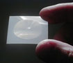
The IR-diod is most sensitive to IR-changes. To gain sensitivity, filtering and IR-viewing angle, one use a lens in front of the IR-diod. This lens is called fresne lens. It is the window you see on the alarms. The output signal from the IR-diod has to be amplified to obtain a useful signal. The next block is a preamplifier. This amplifier amplify the signal about 70dB or 5000 times. Since the IR-change is quit low in frequency, the amplifier is built to work with low frequency about 1-5Hz. Imagin a person who walks towards the detector, then the emitted IR from the person is focused into the fresne-lens with a low frequency. At the output of the amplifier we have a DC signal wich is 2.5V +/- 1V depending on the IR-diod. The output goes to an A/D converter and a microcontroller handles the rest.

    Why I have used this configuration is because I want a very sensitive and intelligent unit. One could have made a voltage comparator to check if the IR-detector level is changing. What I noticed was that the DC-level was changing a little and with very low frequency. There is also noise comming from the IR-diod wich adds to the signal. What I have done is that the A/D samples the signal from the IR-diod 8 time per second. In the CPU I calculate the mean value of the 8 last samples and if the last sample has a larger/smaller value than a predefined level, it will signal a trigg. It might sound difficult, but look at the pic below and I will explain in more details:


    The blue line represent every sample, and as you can see there is a large noise level. In this example it is about +/- 300mV. (In reality I measured the noise to about 66mV in my case!) The red line is the avarage value of the 8 last sample. As you can see the DC-level (red curve) is not flat, it is rising slowly. In reality the DC-level is more stable, but it can change up and down a bit depending on the background light and teperature in the surounding area. As you can see in the pic there is a sample wich is standing out with a higher level than the noise. This will be a trigg. To simplify everything one could say that I use a software calculated trigging system wich test every sample with the calculated avarage samples. This will give a very sensitive trigging system and it will self adjust to its enviroment as dark or light rooms. The system also need no manual trimming. Isn't that marvelous.

    How to set the trigging level then?
    The trigging level should of course be higher than the noise level, or else it will trigg continously. Since I use a 12 bit AD and my calculating system is for 12 bit you will need 2 bytes to set the trigging level. The two bytes are programmed into the EEPROM when you program the circuit.
    High byte : EEPROM adress 0
    Low byte : EEPROM adress 1

    The A/D use 5V as full scale wich means that each A/D bit is 5V / 4096 = 1.22mV
    In my example the noise was 300mV =>245 decimal. or F5 hex
    Adress 0 = should be programmed with 00 hex.
    Adress 1 = should be programmed with F5 hex.
    The system would probably be very sensitive now, so may be you should have add some saftey marginal as well.

    When a trigg has occured the CPU power upp the transmitter and set the DTMF circuit to send some data. The DTMF (dual Tone Modulated Frequency) circuit is a circuit wich code data into 2 tones with different frequencies. You have probably heard this when you diale on your phone. The tones you hear are representing the number you are dialing.

    Why using DTMF ?

    In the receiver I have a circuit (MT8880) that can decode DTMF and this circuit is constructed to work even with bad sound quality and high noise levels. If I wouldn't use DTMF the receiver would need a very good signal with low noise level to be able to decode the pure data.
    So, by using DTMF I will not be so dependent on the quality of the signal wich means the distance between the transmitter and the receiver can increase, and I don't have to consider so much about antenna position either.
    I also don't want the reciver to trigg and give false alarm just because there is noise or other unwanted signals.

    To keep the power consumption down, the transmitter unit will be powered only when it should transmitt (150 ms).
    To know if the receiver can hear the transmitter I have also implemented a "keep in touch" signal in the IR-unit wich will wake the transmitter every 10 second and send a short "OK" signal to the receiver.
    The receiver will have a "guard watch" wich will listen and if it won't detect the "OK" signal every 10:th second, it will give you an alarm saying that there is no connection between the two units.
    May be they are to far away from eachother or may be the power has failed.

    Do you think it sounds difficult with all digital thing I have implemented?
    I can ensure you that you don't have to think about it. Everything is in the software.
    The only thing you need to do is to program the circuit and have fun.


    Schematic
    Okey, lets have a look at the schematic.


    Power supply:
    At the bottom right side you can see the main power. It is a 9V battery. There is also a button (ON/OFF button). Imagin that the power is off. The button is pressed and power goes up in D1 to the 7805 circuit wich power the PIC16F84. The first thing the PIC does is to set RB4 (pin 10) high. The NPN transitor (Q1) will make Q2 draw power to the 7805. The system is now self supplying and you can let the button go. The RB2 (pin 8) input on the PIC16F84, will monitor the button status. If you press the button again, this input will go high, and the PIC will know that you want to turn the system off.
    The RB4 (pin 10) will go low as soon as you let the button go, the system will kill its own power supply.

    IR-part:
    The IR-diod I use is CLS172. I guess you can use almost any one. It is powered with 5V and the output signal is first filtered, and the signal is added to a 2.5V bias. I use a simple OP to amplify the signal. The gain is set by the ration of two resistors, 1M/200 Ohm = 5000 times.
    At pin 6 of the OP, you have an output of 2.5 VDC bias and a AC signal of 0.5-2Vpp depending on the incoming IR to the diod. You can connect an oscilloscop here and use a very slow sweep time, and monitor the output signal.
    Put the fresne-lens over the IR-diod and move anything hot in front of the detector. Watch the oscilloscope and see how the signal changes in amplitud. 'You really should test the IR-unit befor you go any futher in the project.

    A/D-part:
    The A/D is my commonly used AD1286 wich is 12 bit. The Vref is set to 5V by a resistor to Vcc. The control signals to/from the A/D are directly connected to the PIC.

    PIC16F84-part:
    This unit get the info from the A/D and it also controls the powersupply.
    At RB1 (pin 7) I have added an piezo sounder wich gives you a little beep when the power is turned on, and two beeps when you shut the power down. I also use this beeper for other purpose, read more in the extra option section.
    At RA1 (pin 18) I have a LED. You can read more about this LED in the extra option section. The PIC runs from a crystal 3.57954MHz. It is important to use this exact frequency, because the DTMF circuit is also using this frequency.

    DTMF-part:
    The DTMF circuit use the 3.57954MHz frequency to make the dual tones. This DTMF circuit is in a DIL 20 capsel and is controlled by a parallel interface. The output from the DTMF circuit (pin 8) has 2.6Vpp and a DC bias of 2.5V. This level is quit large and could modulate the transmitter as it is, but I have choosen to amplify the signal even more. before it modulates the FM transmitter.
    I use a simple NPN (BC817-25) transistor to gain the signal. The resistor R1 and resistor R4 set the gain and the DC-bias. If you use another transistor you might have to change the values of these two resistors. Use an oscilloscope connected to the collector. You can use two potensiometers (500 ohm and 200k) instead of R1 and R4. R1 will set the DC bias and R4 will set the gain. Make sure you get a nice shape of the amplified signal.

    If you look at the schematic you will se that from pin 8 at MT8880 I divide the output signal with two resistors 10k and 1k. The output signal at pin 8 is 2.6Vpp and after the divider it will be 230mVpp. The signal passes C4 to remove any DC bias and the transistor with R1 and R2 will amplify the signal to 4.8Vpp with a DC bias of 4.4V.
    You may now wonder why I first divid the signal with two resistors and then amplify it. Well the reason was that I wanted as large DTMF signal as possible and since the output signal was 2.6Vpp I had to divid it down to make the transistor amplifyer work properly. The values of R1 and R2 I have choosen, gives me a gain of 21 times (26dB) and a DC bias of 4.4V. If the output signal from the MT8880 at pin 8 is 2.6Vpp and then divided to 230mVpp, (red curve) it will be amplified to 4.8Vpp (green curve) at the colector and the signal will swing around the 4.4V bias.

    Remember, the voltage level at the kathod of the varicap diod BB132 modulate the frequency. The voltage here can theoreticaly be from 0 to 9V and the frequency change will be in that case a few kiloherts. If you use to low modulating voltage the Frequency Modulation will be less.
    What we want is a high modulation because it will give better signal to noise performance.

    One possible modification:
    You can exclude R1, R2, C4 and the transistor.
    Just connect the left side of the 110k resistor to pin8 directly on MT8880. Since the DTMF signal is 2.6Vpp with 4.4V bias, you will have a good modulation.

    Remember that during operation mode, the DTMF tones is about 150mS long and the power to the transmitter part will only be on during the complete transmision. It can be difficult to catch the signals on an oscilloscope.

    Therefore have I added a test program for the unit. This test program will make the LED blink, beep the beeper and it will turn on the power to the transmitter and it will also continously send different DTMF tones. You can use this test program to calibrate and check the system.
    This testing program will not use the AD part and the IR-Diod. You don't need to program the trigg level as well.
    When you are satisfied with the testing you can program the unit with the sharp program.
    Both program can be found at the bottom of this page.

    Transmitter-part:
    This part has ben described in many of my other constructions so please read all the details here :
    50 MHz crystal controlled bugg
    50MHz Power Amplifier


    Transmitter-power supply:
    PIC16F84 control the power +9V to the transmitter unit by two transistors, a NPN Q3 and a PNP Q4. RB3 (Pin 9) control the power.
    The power consumption during transmitting data is 200-300mA. The RF-output power is 100mW. This unit will work up to 4000m in-line-of sight. If you are in concret buildings or in the city with lots of surounding buildings, it will transmitt some hundred meter. I believe this range will be good enough don't you think!

    Extra options
    What does extra options means. Well, this IR-detector is basically a transmitter wich can transmitt data over long distance to a receiver. The transmitter will send data only when the IR-diod detect a moving object.
    I also wanted this unit to work as a pager or remote control unit. There is a power button on the box. Why not use this button, so if anyone want to page you he/she could just press this button and you would get a paging-beep-signal in your receiver.
    The IR-part must of course be disconnected or else it will trigg when someone holds the unit.

    All this can be done in a software change. How?
    When you start the unit you simply pressed the power button. If you hold the button pressed for 2 sec the unit will go over to Remote Control Mode. The IR-function will be disconnected and you will hear some beeping tones indicating Remote Control Mode. The LED will now blink and if you press the button again the unit will send a paging signal. The receiver will automatically understand, and beep some tones to get attention.
    To turn of the power you must hold the power button pressed for 2 sec and then you will hear two short beeps and the unit will sleep shut down.

    Building and testing
    I would suggest that you build the IR-part first and test it with an oscilloscop. Set the sweep time to 1 sec/ div and 5V DC. Move something hot in front of the diod (Fresne lens) and make sure you got a good signal on the scope. You can also walk pass by the lens to make sure it will give a strong signal from your body heat. (Keep your clothes on!)
    Next section is to get the transmitter working. It should not be so difficult. The best is to use an oscilloscop to make sure it oscillate as it should. You will have to tune the coils and the cap for best performance.
    The last part is the PIC. Use the test program I have added and you will not have so much difficult to get it working.

    Power consumption
    The power consumption is about 7mA during sleeping time. When the circuit measure the IR it draw about 12mA. The time it measure the IR (8 time / sec) is very short (1ms), so the total consumption is still low. When the unit transmitt it consume up to 300mA depending on the resistor R3 A lower resistor value will give higher output power and draw more current. Rememeber if you make the unit draw much current you also need a battery wich can deliver that curren or else you might get a voltage drop wich can cause instability in the unit. The transmitting time is set to 150mS.

    Transmitting Protocol
    The protocol is simple:
    I use two digit to make a call. One could use more to get a safer transmision, but in this version I use only 2. The transmitter starts and after 2.5ms the DTMF-circuit send the first digit for 50ms. After first digit comes a 50ms pause and then comes the next digit also for 50ms. After the last digit the power to the transmitter is shut down.
    The total transmision time is about 150ms.

    The codes:
    I choose the two key-numbers so the DTMF frequency is far from eachother.
    One could probably use any number.
    Code 19 Tell that there has been a IR-detection.
    Code 18 "keep in touch" (sends every 10 second)
    Code 17 "beep" (Remote mode)

    Antenna tuning
    Puhh, here comes the boring part for all homebrewers who doesn't have sofisticated equipments!
    Don't worry, I will explain to you in detail how to make the antenna tuning part working with the antenna to obtain best performance.
    I did several experiment with this tuning unit. In the receiver unit you have an RSSI output and you also has an audio output. So what I did was to tune the transmitter and then I went outside and into my car and drove away. I measured the RRSI level and listened to the signal and noticed how far away I could go and still have an acceptable signal. I even tested without any capacitors and coil. The transmitter work good even without any filter, but when I tuned the antenna filter, the signal was improved and the transmitting distance increased a bit. It is not so easy to get full power out of a battery driven transmitter since most 9V battery doesn't give so much current.

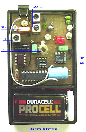
    The pic at right shows the antenna tuning part from the larg schematic.
    You can se two variable capacitor and a coil. What we are going to do is to tune the antenna for best performance. In my test i noticed that the capacitance in the two variable capacitor are very dependent on the antenna length. That is why I have choosen to use capacitor with large range( 6-250pF). I have found the variable capacitor C2 and C3 in cheap radios where they have been used to set the radio stations. They are quit big (2x2cm). I will use this two large capacitor to find the match and then I will substitute them with smaller type plus fixed capacitance if it is needed.
    In my experimets I used a 1/4 wave whip antenna. This antenna typ has an impedance about 50 ohm. 1/4 wave at 50MHz is about 1.5m. This length is not practical to use in a portable system as this will be, but during my test I used this length.

    How to find the strongest signal?
    I guess you could use a SWR meter , but I don't have one so I tuned it in another way (see fig below).


    In the receiver unit is a RSSI output. This output will give an indication how strong the received signal is. I have a red LED-voltmeter and I simply connect this voltmeter to the RSSI output and put the receiver some meters away from my transmitter. I can now tune the capacitor C2 and C3 by looking a the voltage level on the LED display at the receiver.
    When I used a 1/4 wave antenna C2 was about 40pF and C3 was 15pF. When I used a 1/8 wave antenna I had to increase C2 to about 200pF and C3 to 20pF to obtain strongest signal. The strengt with the 1/8 wave antenna was not as good as the 1/4 wave. When you have set the antenna length and you have tuned C2 and C3 I suggest you measure the capacitance in C2 and C3 and simply substitue them with smaller pices and fixed values. 1/8 wave antenna is about 75cm and that will do.

    Download PIC16F84 program (INHX8M format)
    Ir_txr_t.zip Test Program (The file Ir_txr_t.hex is zipped!)
    Ir_txr.zip Sharp Program (The file Ir_txr.hex is zipped!)

    Download some datasheets
    07312861.pdf Datasheets for AD1286.pdf
    07303688.pdf Datasheets for MT8880 DTMF circuit
    07522402.pdf Datasheets for CSL172 IR sensor

    Final word
    I hope you will enjoy this 007-project.
    I also hope I have given you some new ideas and knowledge.
    You can always mail me if there is anything unclear.
    In some case I can help you with components if you can't find them.

    I wish you good luck with your projects and thanks for visit my page.


    Back to main Page  |  Contact Me  |  Cheap components

    Copyright © Last modified on 28th May 2002.