LC-meter
Inductors are not the most popular parts in constructions.
The bad reputation comes from the lack of good measuring tools.
This project will explain how to build a very accurate and simple inductance, and capacitance measuring tool.
You will also find information about the theory and math behind the measurements.
I have also developed a totally new software for this project.
Expected accuracy is +/- 1% of reading +/- 0.1pF or +/- 5nH
All contribution to this page are most welcome!
Background
Why did I choose to build a LC meter from scratch,
when I could find so many projects out there on the internet? The answer is simple:
Most of the projects does not explain the theory and worst of all, most of them use wrong calculations in the calibration procedures.
Some KITs use jumpers to set the prefix range as pF, nF, uF, nH, uH, mH.
I want a LC meter which calculate correct and handle everything automatically, even the prefix should be handled automatically!
So, the only way to build a fully functional LC-meter is to build one myself (as usual).
First I want to emphasise that the main LC-oscillator is NOT my construction.
Why invent the wheel two times?(There is some evidence that the idea was described by Dr. Hegewald)
Although, I did have to develop the hardware around the oscillator and a new working software,
which would measure frequencies and take all the theory into consideration.
Since we are dealing with math and many calculations, I had to implement floating point algorithm into the micro controller.
I now remember why I prefer developing hardware than software :-)
Well it took me eight months to develop, and many cups of coffee.
Specification of this LC-meter Range:
0 nH to 10mH, resolution 2nH
0 pF to 10uF, resolution 0.1pF
Accuracy:
1% of reading typical
Calibration:
Automatically calibration built in
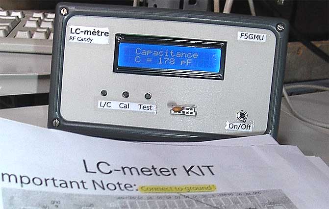
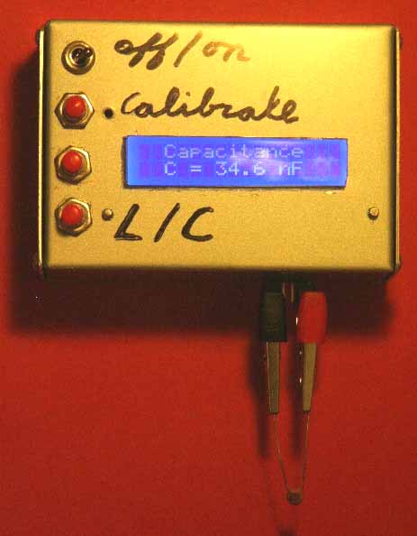
Display:
2 line 16 white chars, blue backlight display
Automatic prefix pF, nF, uF, nH, uH, mH
Software:
Easy to learn and to handle
Testing program built in
Hardware:
Easy to build and to test
The theory behind the measurements
This section will involve lot of math and theory.
I was very lucky to have a great teacher, who really knew how to catch people's attention :-)
If you don't like math, you can skip this section and jump down to the party below. Click here to jump down!
The theory is not so complex at all so don’t worry.
LC-meter will work equally good with or without your knowledge about the theory.
The LC – meter is actually an LC oscillator based around the familiar comparator circuit LM 311.
I have not changed the LC oscillator much from others projects, since this is an excellent oscillator.
We are now dealing with an LC oscillator. The oscillating part is a parallel LC tank.
We will use the well known parallel resonance formula (see formula 1. below).
The formula say that if you connect an inductor parallel with a capacitor, it will have a resonance frequency (f). L is the inductance in the resonance circuit. C is the total capacitance in the resonance circuit.
If we connect an unknown capacitor called Cx parallel to C, we will get a lower resonance frequency (f2), due to
the increased capacitance.
The formula would then look like this:
As you see, we have a new resonance frequency (f2) and you can see how Cx has been added to C.
Lets play around with the two resonance formulas and divide f1 with f2. (formula 3.)
The inductance (L) in the formula disappeared!
We now have a relationship between capacitances and frequency, Great! (formula 4.)
So what does formula 4 show anyway?
Well, if we know the value of C, and we can measure f1 and f2, we will be able to use formula 4 to calculate Cx.
C is equal to all the parallel capacitance in the LC tank, but we do not know the C of the construction do we?
No we do not, but by making a calibration with a well known Cx, we can go backward and calculate C.
Don’t feel confused, I will explain this calibration phase more:
Befor any measurement can be done, the LC meter need to perform a calibration to find out the constant value of C.
To find C, we use the formula 4 and break out C. (formula 5.)
The procedure start to measure f1 when only C exist.
Then we add a well known capacitor Cx (reference capacitor) to the LC unit and measure the frequency again (f2).
Since we know Cx (reference capacitor) and we have measured both f1 and f2, the micro controller will be able to calculate the constant value of C.
The procedure above is called the calibration phase.
In reality it is very easy, all you need to do is to press a button called calibrate and the micro controller handles it all for you!
What is important is that you use a very good capacitor for the calibration, else you will add error to measurement.
In my construction I use 440pF 0.5%. The calibration capacitor is mounted on the PCB and will be added automatically with a relay. (more info later)
Now, when the micro controller knows the constant value of C, you can use formula 4 to measure any unknown capacitor at Cx.
Are you confused enough? (* smiling *)
Practical example:
To make this even more understandable, I will make a small calculation example to verify the calibration formula:
When I have no capacitor (Cx) connected to my LC-oscillator, I measure 610331Hz.
I connect a well known capacitor (Cx) of 440pF 0.5% to the LC-oscillator and now the frequency drop to 508609 Hz.
Let’s use the calibration formula 5, above to calculate the value of C in the LC unit.
f1 = 610331, f2 = 508609 Hz, Cx = 440pF. The formula gives C to be 1000pF.
(remember that C is constant and equal to all the parallel capacitance in the LC tank)
Now, when I know C, let’s check if our calculation is correct.
In my measuring example I had an inductor of 68uH in the LC-oscillator.
I use the parallel resonance formula 1 :
When no Cx capacitor is connected I have L= 68uH and C=1000 pF, this gives resonance frequency = 610 331 Hz
When Cx capacitor is connected I have L= 68uH and C=1000 pF + Cx = 1440pF, this gives resonance frequency = 508609 Hz
If we compare the calculated frequencies with the measured we can see that the calculation of C = 1000pF was correct. Great!
Now when we know the value of C, we can use formula 4, to measure any unknown value of Cx.
Lets look at the theory how to measure inductance.
We will still use the parallel resonance formula (formula 1,) but in this case we will add an unknown inductance Lx in serial with the L1.
We will have two states.
One when we only have the main inductor L1 connected with C, and a second state when we have the extra inductor Lx in serial with L1.
As you understand we will get two different resonance frequencies.
First state is when I only have L1 connected to C, and the frequency f1 will be produced from the LC-oscillator.
Formula 6 show you how I break out L1 from the parallel resonance formula. Only L1 exist. (Lx = 0)
Second state is when I add Lx in serial with L1 to form L2. Since the inductance increase the frequency (f2) will be produced from the LC-oscillator.
Formula 7 show you how I break out L2 from the parallel resonance formula. L1 and Lx are connected in serial to form L2
What we search for is Lx. (formula 8.). I put formula 6 and 7 into formula 8 and get formula 9.
After cleaning up we get formula 10. Let's look at this formula in more details. As you can see the main inductor L1 is gone.
To measure Lx, we only need to know the C, f1 and f2 of the LC-oscillator.
C will be calculated in the calibration phase (as I described earlier).
f1 will be measured when the input is short circuited.
f2 will be measured when Lx is connected to the input.
Conclusion:
It is possible to measure both capacitance and inductance as long as you have an accurate reference capacitor Cx for
calibration of your measuring LC-meter.
When it is calibrated you can connect either an unknown capacitor or inductor and measure its value.
In this construction I have implemented the calibration so you only need to push a button. The microcontroller will then do all the work for you.
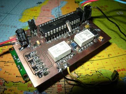
Hardware and schematic
The main part of this project is a LCD, PIC16F870 and an oscillator LM311.
The LCD is a standard 2 line 16 chars display connected in 4-wire mode to the PIC.
At the bottom you will find a 4.000 MHz crystal to run the PIC.
The heart of this construction is the LC oscillator based around IC2. The frequency pops out at pin 7 and then enters the PIC at pin 11.
Two relays have been added to make the measurement more automatic, and they will also prevent stray inductance/capacitance.
Many LC meters use manually switches which will be conected with long wires. I prefer relays which will improve the accuracy and keep the stray
capacitance/inductance down to a minimum level.
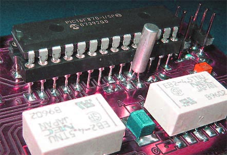
The two relays are controlled by 4 transistors. The reason why I choose this construction was to keep the current consumption
to a constant low level. If the current fluctuates, it will affect the measurement which is not good.
The relays I use are a bit different since they have "double-coil latch types".
REL1 choose to measure between Inductance or Capacitance. (see bottom of schematic).
When you measure inductance, REL1 will add the unknown inductor Lx in serial with L1.
When you measure capacitance, REL1 will add the unknown capacitor in parallell with Cx.
REL 2 has only one function and that is to add the reference capacitor during the calibration phase.
C4, R13 is added to make sure the oscillator starts up correctly.
At the left side of the schematic you find the LCD display and you will also find three inputs.
You should connect 3 buttons to the unit. (L/C, Calibration, Test input)
L2 and C7 is added to make the power line smooth and reject RF.
A jumper J1 is added to choose if you want strong backlight or not.
If jumper J1 is disconnected the LCD will have soft backlight because a low current will pass through R14.
If jumper J1 is connected you will have strong backlight.
Above you can download a (pdf) filer which is the black PCB. The PCB is mirrored because the
printed side should be faced down the board during UV exposure.
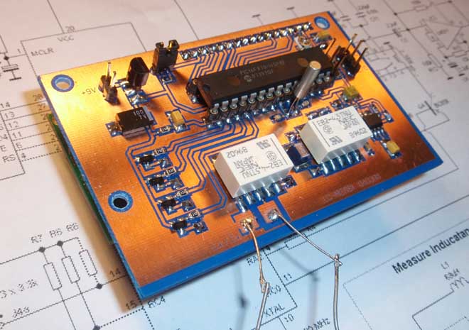
To the right you will find a pic showing the assembly of all components on the same board.
This is how the real board should look when you are going to solder the components.
It is a board made for surface mounted components, so the copper is on the top layer.
Grey area is copper and each component is drawn in different colors to make it easy for you to identify.
The scale of the pdf is 1:1 and the picture at right is magnified with 4 times.
Click on the picture to enlarge it.
Assembly
Good grounding is very important in a RF system. I use bottom layer as Ground and I connect it
with the top layer at three places (via-holes) to get a good grounding.
Drill a small hole through the PCB and solder a wire in each via-hole to connect the top layer with the bottom layer which is the
ground layer. The three via-holes can easy be found on the PCB and in the assembly pic at right, they are
labelled "GND" and marked with red colour. Drill the remaining 16 holes for the Pin Header 2.54mm which will connect
the LCD to the PCB. Since the backplane of the PCB is Ground you must make sure there is no connecting copper to the Pin
Header 2.54mm at the backside. Easiest way is to remove the copper at the backside is to use a larger drill (3mm) and drill a bit in the holes at the
backside of the PCB.
Soldering and testing:
The soldering of this unit is pretty basic if you solder the parts in correct order.
I advise you to follow the instruction below.
Start soldering R6, R7, R8, J2a, J3a, J4a, J2b, J3b, J4b, P1 C2, C6 and then 28 pin dip socket (The socket is soldered directly to the component side)
Then X1, C8, C9, C10, C11, C7, R12, R10, L2, R9, R11, R13, C4, C12, C5 and IC2.
REL1, REL2, L1, Q3, Q1, Q4, Q2, R1, R2, R3, R4, R5, C3, R14, J1, V1.
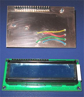
Front side:
Before the LCD is soldered you should connect the 4 wires from the transistors Q1-Q4 to the relays.
Look at photo below how I connect the 4 wires A, B, C, D.(You can also find them in the schematic)
Connect the LCD to the PCB with the (Pin Header 2.54mm).
Power up
Take some time and verify that you have no soldering bridges! Do not put PIC16F870 into its socket yet!
Connect power and control that you have stable + 5V at the power line and display.
Toggle RA1 (pin 3) low -> high, then toggle RA3 (pin 5) low -> high.
The REL1 should click every time, if not then the problem is around Q1 or Q2.
Toggle RA0 (pin 2) low -> high, then toggle RA2 (pin 4) low -> high.
The REL2 should click every time, if not then the problem is around Q3 or Q4.
Power off the unit and put PIC16F870 into its socket, and connect power again.
P1 will need to be adjusted to give good contrast of the display. The voltage at pin 3 of the LCD should be about 0.70V-0.75V.
If everything is OK you should see text on the LCD display.
There is a test function built in this LC-meter, and below you can read all details how to use it.
PIC Software
Let's have a look of the different menu choices of this LC-meter.
All settings are made by the two switches L/C and Calibrate.
The unit will always remember the last settings even if power is switched off.
Figure below show all the different menu choices.
Measure Capacitance:
When the power is applied the LC-meter will enter menu 1. The display will show Capacitance measurement
The LC-meter then enters menu 2.
Here you are asked to Open circuit the input (no capacitor is connected to the input).
When this is done, you should press the calibration button.
The LC-meter will start the calibration procedure, and after 2 seconds the unit is ready and shows menu 3.
The LC-meter then starts to measure the input and you can connect the unknown capacitor.
Every second, you will get a new measurement (menu 4).
Measure Inductance:
When the power is applied the LC-meter will enter menu 1. The display will show Inductance measurement
The LC-meter then enter2 menu 2.
Here you are asked to Shortcircuit the input (the input is connected to ground).
When this is done, you should press the calibration button.
The LC-meter will start the calibration procedure, and after 2 seconds the unit is ready and shows menu 3.
The LC-meter then starts to measure the input and you can connect the unknown inductor.
Every second, you will get a new measurement (menu 4).
At any time you can press the calibration button to make a new calibration.
At any time you can press the L/C button to toggle between Capacitance and Inductance measurement.
Testing
There is one more menu in this LC meter, and that is the testing menu.
I have added this function to make the building and testing easier for you.(An option most other KITs have forgotten)
There is only one way to enter the testing menu, and that is to press the button Test during power up.
The display will then toggle between the two pictures below.
The input should not be connected to any object.
The LC-meter starts to measure f1 (main oscillation).
After 1 second, the relay 2 will connect the reference capacitor and the unit will make a new measurement f2.
After another second the unit will go back to measure f1 and it all repeats until you press Test button again.
As you can see, my measurement was f1=896 344 Hz, and f2=652 311 Hz
There can be variation in frequency from kit to kit, but in general you should have f1=800-900kHz and f2=600-700kHz
Accurate measurement
To get accurate measurements it is very important to keep wires as short as possible.
It is especially important when it comes to measuring small inductance.
A straight wire of 10 mm can add up to 10-15nH, so it is very important to keep wires as short as possible during measurement.
Temperature variation will also affect the measurement a little bit, since it will change the leakage current in LM311.
Even if the temperature variation may be small, it is always good to perform calibration as often as possible.
If you follow these few suggestions, you will be able to measure inductance and capacitance with accuracy beyond your dreams.
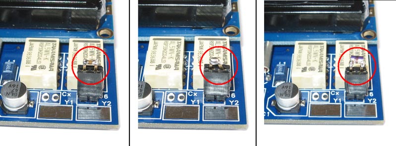
Picture below show how I measure sensitive parts with high accuracy.
The left picture show how I measure a small smd capacitor. You can see that i have soldered the capacitor on to a 2 pin female header.
The middle picture show another pin header used to shortcircuit the input for inductance calibration.
The right picture show a third pin header where I have soldered a small smd inductor ready for measurement.
The procedure is very simple, I attach the shortcircuit pin header and calibrate, after that I switch to the pin header with the inductor.
This is only ONE way to measure with high accuracy, I am sure there are many more ways.
Trouble Shooting section
If you get a problem with your unit, you might find this section helpful.
I get no text on my display!
Make sure you have +5V to pin 2 of the LCD and that the background light is working.
You should now test that the contrast voltage of the LCD is ok.
The voltage at pin 3 of the LCD should be about 0.70V to 0.75V.
This will give good contrast!
You should also make sure you have 5, 7, 8, 9, 10 to ground.
Now, you should test that the data signals is arriving to the LCD.
Look at the signal of pin 14, 13, 12, 11, 6 and 4 and make sure you measure on the LCD.
I often use a small speaker or piezo element and listen to the signals.
You should hear clicking sound or beeping tones when the display is updating or during power on.
If you don't have any data communication to the LCD the problem is with the PIC16F870, next section.
My PIC16F870 is not working!
Make sure you have +5V to pin 20 of the PIC.
You should test that the Reset (pin 1) goes high when power is turned on.
The oscillator should be running at 4 MHz. (Test with oscilloscope or equal equipment)
Make sure that RC3, RC4, RC5 is high goes low when button is pressed.
Check that you do not have any soldering bridges between legs or to ground.
My oscillator is not working!
Run the test program to check if the oscillator is working, or use an external frequency counter/oscilloscope and check pin 7 of IC2.
You should measure about 600-900kHz
Check that you have +5V volt to pin 8 of IC2.
Make sure you have assembled the 2 relays in correct direction.
Again check for soldering bridges!
Remove the PIC from its DIP socket and toggle RA1 (pin 3) low -> high, then toggle RA3 (pin 5) low -> high.
The REL1 should click every time, if not then the problem is around Q1 or Q2.
Toggle RA0 (pin 2) low -> high, then toggle RA2 (pin 4) low -> high.
The REL2 should click every time, if not then the problem is around Q3 or Q4.
Final word
This project looked to be a simple project, but it took me four prototypes and eight month to finish it.
The most difficult part was to develop the software, and to make it fit into the PIC16F870.
When I made my first measurements with the unit I was amazed how well it worked, and how accurate the measurement become.
One can find some cheap capacitance measuring tools on the market, but when it comes to inductance it is much more difficult.
This project is a very helpful tool to measure both capacitance and inductance.
You can now measure the inductance of your self made air-inductors and cans.
Photo Gallery
Some assembled counters people have mailed me. Please mail me more.
 LC-meter
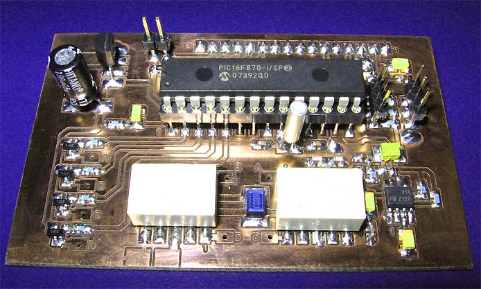 Specification of this LC-meter
 The theory behind the measurements