Click on the pic to see a largeer photo with info. Super Scanner 45-860MHz with 0.01Hz stepsize.
To everybodys joy, I have finally built the Super Scanner.
This receiver is based on a TV tuner, a DDS circuit and a radio circuit.
Together it will be like T + N + T.
The receiver is so powerful, you must use safetyglasses while using it!
This receiver will work from 45 to 860 MHz and the step size can be down to 0.01Hz
Why not use this receiver as a Spectrum Analyzer or a NOAA satelit receiver?
How about that!
All contribution to this page are most welcome!

Background
Put your goggles on! Why making life more complex than it is?
That was my guidline through this project. Why building a receiver, when you can reuse a tuner. Said and done. The hart of this receiver is a TV or VCR tuner. The tuner is a digitally type, which means that the received frequency should be programmed into the tuner via I2C interface.
Don't stop reading now! it is not difficult and I have prepared everything for you, so keep reading. The smallest stepsize of a tuner is 31.25kHz, 50kHz or 62.5kHz. This is far to wide stepsize, specially if you are looking for narrow band signals. To solve this matter I have added a second mixer using a DDS as osc. With the DDS you can step inside the 62.5kHz, 50kHz or 31.25 kHz window. The smallest stepsize this DDS configuration can perform i 0.01Hz. In most case 0.01Hz will not be practical, so in my software I will use the smallest stepsize to 1Hz.

First some info about TV Tuner
I just love TV tuners and that Is why I now will explain them for you.
I have written before about tuner, but you can never write to much about them so here we go again:
What does a tune look like?
Well, crack open your VCR or TV and look for a shiny methalic box (*smiling*). When you have found it you can open it, and inside it will look like hundreds of ants. Well, it is surface mounted components. If they are moving around you should probably get rid of the box or examin your head.
The tuner is basically a down converter. It convert down the input RF to a frequency at 34-38.9MHz (European standard). Some newer tuners has internal demodulator and their output signals are pure video and audio.
The frequency you want to downconvert can be set in two ways analog or digital way.

The input frequency is set to tree bands:

VLF 48-180MHz
VHF 160-470MHz
UHF430-860MHz

The analogue tuners use an input voltage 0-28V to control the tuner VCO (Voltage Controlled Oscillator) and there is also 3 pin to select band (see fig at right). The tuning voltage also control the input filter to the tuner. The input RF is mixed with the VCO signal and the output product (IF) is set to 38.9MHz.
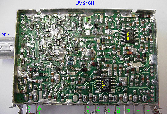
The disadvantage of the analogue tuner is that it is difficult to get stable tuning voltage to the VCO and to know wich frequency you are receiving.

The digital tuner works in another way, they use a PLL synthesizer circuit to set the frequency. The synthesizer can be programmed to any frequency in the range of 45 to 860MHz. The synthesizer sens the frequency from the tuner VCO and compare it with the programmed frequency. The circuit will then regulated the tuning voltage until the frequency from the VCO and the programmed are in phase with eachother. The bands and the frequency is programmed by an I2C interface. The digital tuner is very exact in frequency and is very stable. The only disadvantage with this type of tuner is that you need digital logic to program the tuner. I usually use a PIC controller to program my digital tuners.

Lets have a look at some tuners: UV916 and a noname tuner
In most cases you will have difficult to see the lable of the tuner or even find a lable. I don't know why they are so lousy to identify the tuners. I have collected over 50 tuners from different TV and VCR and I have manage to find about 10 with proper lable. Don't worry yet! Even if you wont find any info about the tuner you can open it and identify the circuits. Most often you will find a PLL synthesizer and one demodulator/mixer circuit. Try to find the datasheets over the PLL and you will understand how to program the tuner.
One common tuner is UV916. The photo below is a UV916H /UV916 E tuner. I will help you to identify all parts:


This tuner is based on two circuits. TDA5630 "9 V VHF, hyperband and UHF mixer/oscillator for TV and VCR 3-band tuners" and TSA5512 "1.3 GHz Bidirectional I2C-buscontrolled synthesizer".
The TSA5512 circuit is digitally programmed to a desired frequency and the PLL set the Vtuning voltage to the TDA5630 ciruit.
The stepsize of this tuner is fixed to 62.5kHz. This tuner has 9 input and a shield (shield=ground).

  • AGC = Automatic Gain Control. Apply a voltage 0 to 12V will set the gain of the preamplifier.

  • + 12V = Powersupply to the preamplifier and the TDA5630 circuit.

  • + 33V = Powersupply to the PLL tuning system.

  • + 5V = Powersupply to the PLL synthesizer.

  • SCL = I2C clock to the PLL synthesizer.

  • SDA = I2C data to the PLL synthesizer.

  • AS = Adress selection for the tuner (Are used with MA1 and MA0 see page 8 datasheets)

  • IF = IF out

  • IF = IF out


  • One tricky thing with tuners is to set the desired band. The band are selected by programing the port register P0 to P7 in the TSA5512 circuit. The UV916 band is following:
    BAND P7 P6 P5 P4 P3 P2 P1 P0
    LOW BAND (60h) 0 1 1 0 0 X X X
    MID BAND (50h) 0 1 0 1 0 X X X
    HIGH BAND (30h) 0 0 1 1 0 X X X


    No name tuner
    Now, lets try to identify the part in a noname tuner I have found. After removing the cover we find two circuits.
    TDA 5630 is the mixer and VCO, the TSA5522 is the PLL synthesizer.
    Click the pic to see a larger photo! If we look into the datasheets for the TSA5522 we will find lot of valuable information. With the datasheeets and by following the strip line of the PCB we can identify the SCL and SDA input. We will also find a pin called P6 which is an input to a 5 level ADC converter which can be used to apply AFC (Automatic Frequency Control) information to the microcontroller. In most cases, you will not use this input and can therefor leave it floating. You will also find a input called AS. By applying a specific voltage to this input you can select several synthesizers (up to 3) in one system. In most cases you will only use one tuner, so you can leave this input floating(set MA1=0 and MA2=1 always valid). The PLL circuit use 5V DC and this input is not so difficult to find. IF you look at page 13 in the datasheets you will see how the PLL works. The PLL use + 33V DC and the pin CP will set the Vtune. By following the strip line in the PCB I find the +33V DC input.
    If we now look into the datasheets for the TDA5630 we find it is using +9V DC and this voltage is found at pin 5 which guids me to the input pin. The last pin can not be found in any datashets and that pin is called AGC input (automatic Gain Control). This pin control the gain of a preamplifier. The input voltage to the AGC will set the gain. A good guidline is to set this input to half the voltage of the system, which would be +6V by two resistor in serie. Most often you will find the ACG input as the first pin closest to the RF input side.
    Now we have identified all input to this unknown tuner. Look into the datasheets to examine and understand the register in the PLL synthesizer circuit TSA5522.

    Block diagram of the Super Receiver
    Blockdiagram of the receiver

    Don't be scared of all filters and mixers, in a few minutes you will understand each of them. The tuner is digital type where the frequency can be controlled via I2C inteface. The smallest frequency step size of the tuner is 62.5 kHz. This stepsize is often to large. The standard stepsize in scanners are 50kHz, 25kHz, 12.5 kHz, and 5kHz and less. In this construction I will let the tuner make the large step in frequency (62.5kHz) and then I will let a DDS controlled osc make the fine step inside the 62.5kHz.

    You can think of it like the fig at right:
    How the frequency is set! You have two knobs. The left (red) is the tuner which can step in 62.5kHz. The right one is the DDS which can step from 0 to 62.49999kHz in 0.011Hz step if you want.In the example I have set the resolution to 1Hz, so the DDS step to 62.499kHz. The formula at bottom of the figure show you how you can set the two knobs to get all wanted frequencies.(In reallity the DDS freq is not from 0 to 62.499kHz it is 5.01375MHz to 5.07625MHz).

    With this two unit (tuner and DDS) you will now be able to scann the complete tuner range from 45-860MHz in 0.011Hz step! To understand this tuner I will explain each block. The output IF (intermediate Frequency) from the tuner is set to 37 MHz (european standard). A sharp filter (SAW) reject all other frequencies. The signal go to the first mixer where it Is mixed with a constant frequency from a crystal oscillator at 42.5 MHz.
    The output product from the first mixer will be 42.5 - 37.0 = 5.5MHz. I use a standard 5.5MHz ceramic filter to filter the signal and reject all other frequencies. This filter should have 100kHz bandwith which is common in TV and VCR.

    Before we look at mixer 2 we will go to the final block which is the demodulator. The demodulator works at 455kHz and before the demodulator you can find a 455kHz ceramic filter. If we lock the DDS frequency to 5.5MHz - 455kHz = 5.045MHz, we will receive exact at the frequency which the tuner is set to. Remember I told you the smallest tuner step is 62.5kHz.
    For the UV916 the stepsize is fixed to 62.5kHz!
    Now, If we change the DDS frequency ±31.25kHz we will be able to use the DDS for finetuning.
    The DDS frequency will be be 5.045MHz ±31.25kHz.

    Can this work?
    It will work perfect if the bandwidth of the 5.5MHz ceramic filter before mixer 2 is wider than 62.5kHz.
    If the bandwidth is smaller than 62.5kHz you will have problem. In my test (pic below) I have found that the 3pin filter has a bandwidth of 600kHz and the 4 pin is about 350kHz so you will probably have no problem. It is not good to have a to wide filter either because you want to damp as much noise as possible and the the smaller bandwidth the better sensitivity of reception.


    Now you think this project have to many mixers and filter and crap..*smiling*.....Don't worry!
    If you use the commonly used circuit MC13135/13136 you will have most of the blocks in the circuit. It contains 1 crystal oscillator, 2 mixer, FM-modulator, RRSI output and lot of other good stuff. The 455kHz ceramic filter, 455kHz quad coil to FM-demodulator can all be found in a cheap radio. The SAW filer, 5.5MHz ceramic filter and the tuner can be found in a broken VCR or TV, I guess you can also find them in a perfect working VCR or TV as well.
    Why not rob them from a perfect working 42" widescreen TV ...*smiling*
    What you need more is the DDS circuit. If you want a free operating unit (non computerized) you can add a LCD display and a keypad. I have drawn the display and the keypad with dotted lines.

    In this project I will build a unit without the display and keypad, because you will have difficult to find the same display I would use and the same goes with the keypad. However, when you get the computer controlled receiver working you can experiment yourself, and add as much as you want. This will give you a great reason to learn how to program a PIC-circuit.. *smiling*

    DDS 9-pol LC filter
    The DDS will not leave a perfect signal. The signal will also contain lot of overtones and other crap from the digital part in the DDS. All this bad signal should be removed to obtain a perfect reception. So, what you need is a output filter between the DDS circuit and the receiver-cicuit. I have choosen to build a 9 pole LP filter. This filter is sharp and will give good attenuation of higher frequencies. This filter use standard componets, so you don't need to make any coils or trim any trimcaps. Easy to build and great performance!
    The coils are standard 4.7uH which can be found at any grosist.
    Ca, Cb and Cc are choosen so you can connect two standard capacitor in parallel. I have written them i gray under each capacitor.


    The fig at right show you the filter respons of the output filter from the the DDS circuit. It is important to attenuate higher frequencies and spurious. This 9 pol filter is sharp and have great attenuation. The working frequency is 5.045MHz ±31.25kHz. The output amplitud at 5MHz is in the range of 155mV rms (yellow arrow). You should make sure that the DDS works properly so I advice you to connect a frequency counter or an oscilloscope at the output of the filter. Make sure you have a nice shape of the signal and that the frequency is working.


    HARDWARE and Schematic
    Klick on the pic to see full scale schematic! You can click on the pic to see the full schematic of the Super Receicer. I will break down this schematic into different sections and explain each of them.

    Tuner section
    In this project I used the commonly used tuner UV916. The AGC is set to +6V via 2 resistors. I have 3 different power supply to the unit(+5, +12 and +33V). The I2C (SCL, SDA) interface is connected to the PIC (RB3 and RB4). P3 is left open and the IF output (37.0MHz) is connected to the SAW filter. The filter has 2 inputs and two outputs. The outputs are connected to the radio circuit. The saw filter is a passband filter from 34-38.9MHz. It will help to remove the mirror frequency.

    DDS section
    The DDS is clocked by a 50MHz crystall module.The PIC program the DDS via RB5, RB6 and RB7). L1 and L2 filter the powersupply to the circuit and separate the analogue and the digital power supply. The output from the DDS is connected to a 300 ohm resistor and after the resistor is the 9 pole filter. This filter is to suppress overtones and glitches from the digital part in the circuit. After the filter you will have a nice shaped periodic signal at 5.045MHz.
    One difficult is that the circuit is a fine pitch circuit, so you must have a sharp soldering tool. Don't be upset when you solder this tiny thing.....

    Radio receiver circuit
    The circuit is a MC13136. At pin 1 and 2 is the oscillator. I use a crystall controlled configuration. At pin 3 you will find an output buffer from the osc. The signal from the tuner passes the SAW filter and into mixer 1 via pin 22. The product from this mixer can be found at pin 20. A 5.5MHz ceramic filter damp all other frequency than 5.5MHz +/- 100kHz. The signal enter mixer 2. At this mixer the signal is mixed with the DDS frequency at pin 6. The product passes a 455kHz ceramic filter and into the FM demodulator. The FM demodulator use a quad coil (pin 13) to demodulate the audio signal. The RSSI Relative Signal Strength Indicator (pin 15-16) will give you a voltage level prortional to the signal trength in dBm. If you use this unit as a spectrum analyzer you can use this output to plot the Y-axle. The X-axle is the frequency. At pin 17 you will find the audio output. It is a low level signal about 50-150mV. I amplify this signal in a simple audio amplifier at the bottom of the schematic.

    RS232 communication:
    I will now explain how the communication between the computer and the Super-tuner works. You don't need to understand this if you don't want, but some people may want to make own controlling program for the super-tuner. The program I have made takes care of everything!
    I have constructed this project so that you must use a computer to set the frequency. In this way you can easally make sure it works and from there you can add display and buttons etc. Finally you might end up with a portable self working unit. But first you need to make sure it works and the easiest way is to let a computer calculate and set the tuner and DDS for proper frequency. To make a computer able to communicate with the unit you need a RS232 to TTL converter which the MAX232 circuit does. I use 19200 baud,even parity,8 bit and 1 star and 1 stop bit (19200,e,8,1). I will now explain the communication protocol.
    The software I have made is general. It means you can use many different tuner with this software. There is totally 9 register which must be set before you can receive anything. The Adressbyte is to set the tuneradress for I2C. Dividerbyte 1 and 2 is to set the frequency in the tuner. The Controlbyte controls PLL currents and other stuff, Portbytes set the acutal receiving band. For more details look into the datasheets over the circuit TSA5512.pdf and you will see every detail of the tuner registers. What the software does is to calculate the content of the 9 registers and send 9 byte to the PIC. The PIC receive the data and convert it to I2C which will program the tuner and serial data for the DDS. You don't have to consider what the PIC does, but it can bee good to understand what happens betwen the computer and the PIC if you want to write your own computer program to control the receiver.

    Conclution:
    To complete a frequency setting of the receiver, you need to send 9 byte to the PIC. The 5 first is to set the tuner (Yellow). The 4 byte after that (Green) is to set the DDS frequency. You can read more details about the DDS under this link. The table above show you the 9 registers. When all 9 byte are sent from the computer, the PIC will make sure that the tuner and DDS is programmed and set to desired values
    .
    Window Software
    I have made a simple window software to control this Super-Receiver. The pic below show the software.


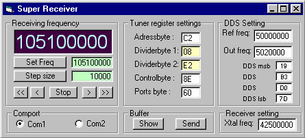
    Download windows software
    supertuner.zip (1.42Mb)
    Click here to go to the software download page!

    I will now explain the different windows:
    Receiving Frequency
    Receiving Frequency is where you can set the frequency you want to receive. You enter a value in the green filed and press Set Freq. You can also set the step size for scanning up/down. The stepsize is entered in the same way as the frequency.
    Comport
    In this window you can select wich port you use to the Super Tuner.
    Tuner register settings
    In this window you can set the register in the tuner. There is two yellow areas which is set automatically and that is Dividerbyte 1 and Dividerbyte 2. These two registers is calculated from the frequency you have entered. Adressbyte, Controlbyte and Ports byte can be entered any time. When you change a value of any of these registers the software will automatically send info to uppdate the tuner.
    Remember to change band (Ports byte) manually when you tune over 150MHz and over 450MHz. The software will not do this automatically!
    DDS Setting
    The DDS need to know the Reference frequency to the DDS. The output frequency is calculated from the receiving frequency you have entered earlier. You will also see the 32 bit divider bits in the DDS, displayed as four bytes.
    Buffer
    The buffers shows the 9 byte which will be sent to the PIC. By pressing send you will send the buffer to the PIC over RS232 line. When ever you change a value the buffer will be sent automatically to the PIC.


    Let's see if the numbers above is correct, shall we!
    IF = Xtal - DDS - 455kHz => 42.5e6 - 5.02e6 - 455e3 = 37.025.000 Hz

    Tuner VCO = 62500 * tuner divider => 62500 * 2274 =142.125.000 Hz

    RF receive = Tuner VCO - IF => 142.125e6 -37.025.e6 = 105.1 MHz
    Looking great!
    That was all about the software!


    Download PIC16F84 program (INHX8M format)
    s_tuner.zip Super tuner program (the hex file is zipped!).

    Download some datasheets
    TSA5512_CNV_3.pdf Datasheets for TSA5512_CNV_3.pdf
    SAW filter information and PDF download SAW filter information and PDF download
    I2C information I2C Bus Technical Overview and FAQ


    My hardware of Super tuner
    I guess you wish to see my hardware for this project. Below I will show you some photo of my late evening soldering.
    Click on the pic to see a larger photo with info. Click on the pic to see a largeer photo with info.
    In this card I have combined surface mounted component and hole mounted components. I have also added a DC-DC converter (top right corner) to obtain the +33V for the tuner. I have also added two 455kHz ceramic filters (One black and one yellow). A relay control which filter that will be used. I have also added another relay to selcet the gain of the demodulation. It is simply done by changing the value of the resistor parallel with the quad coil. The reason to be able to use two ceramic filter and different gain is because I want this card to be able to receiver both narrow band and wide band signal with best performances.

    Building and testing
    Don't connect the radio IC circuit befor all testing is done. I advice you to get the DDS part working first. When you have a proper signal from the DDS with right frequency you can focus on the tuner. At the schematic you will find a test point called TP at the tuner. Connect a DC voltmeter to this point and measure the voltage. The voltage should change when you change tuning frequency for each band. This is an easy way to test that the tuner works properly. Now you can connect the RF IC circuit and test the crystal oscillator.
    Hopefully you will now have a working unit.

    Final word
    This project is a kick start for your tuner projects. This project can grow to almost biblical proportions. Since there are so many keypads and different displays on the market, I have choosen to exclude that and simply control the receiver from a computer.

    You can always mail me if there is anything unclear.

    I wish you good luck with your projects and thanks for visit my page.


    Back to main Page  |  Contact Me  |  Cheap components

    Copyright © Last modified on 10 nov 2002.