This photo show the PCB frontside of the Trinit RF Power Meter. Very small unit and still so powerful. 
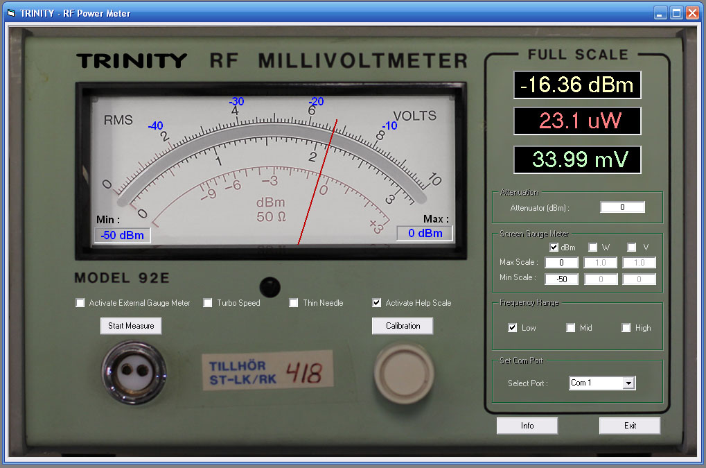
Trinity Virtual RF Power Meter
10 MHz - 2.5 GHz with High dynamic range: 70 dB
High accuracy: ± 0.2 dB


A top quality project designed to obtain maximum performance.
The hardware and software has been chosen carefully to obtain maximum accuracy.
This project comes in KIT version including everything from parts to software's.

Features:
  • Virtual RF Power Meter Instrument with PCB integrated power sensor
  • Wide frequency range 10 MHz to 2.5 GHz.
  • Measure down to - 60 dBm (0.001 uW or 0.225mV)
  • Absolute and relative power measurement
  • Present measurement in dBm, Watt, Volt and Screen Gauge Meter
  • External Gauge Meter for accurate reading
  • 24 Bit A/D resolution of sampled log detector
  • Digital filtering to reject 50/60 Hz noise
  • USB communication to computer

  • Optical communication barrier to prevent noise
  • Internal reference enable self calibration
  • DC input blocking
  • No complex trimming

  • Self-test with LED indication
  • Power supply +9 VDC to +18 VDC
  • Low current consumption typ 30 mA
  • Board size = 3.3" x 1.8" (84 mm x 46 mm)
  • Simple to use, learn and install
  • This project comes only in a KIT version, see more details below

  • All contribution to this page are most welcome!

    Trinity Software Background
    Once again, it is time to develop a new rf power meter. Her name will be Trinity.
    I have done a few rf meter projects earlier, and this project beats them all.
    What I share with many other homebrewers, is the need of an accurate and reliable rf power meter.
    A while ago I was lucky to be working with an old boonton 92E model.
    The instrument has an old fashion gauge meter presenting measurements.
    I loved the instrument and got an idea how to beam it into 20th century in a brand new makeover.
    The Trinity RF Power Meter consists of a circuit board (PCB), and a USB connector.

    The circuit board has a rf input which goes to a logarithmic detector.
    A 24 bits A/D converts the log detector measurement into digital format. Data is then sent to the computer.
    The computer analyse the measurement and present it in many different formats, both in numerical and graphical way.
    Click the picture at right to have a look at the virtual instrument. (More details below)

    I know that some of you prefer analogue instruments, because it is easier to trim rf electronic by looking at a gauge needle.
    I have therefore added an external gauge meter output from the Trinity PCB.
    By connecting a 100 uA gauge meter to this output, you will be able to follow the virtual gauge meter on the screen, with same high resolution and accuracy.


    Click on the schematic to see full size! 
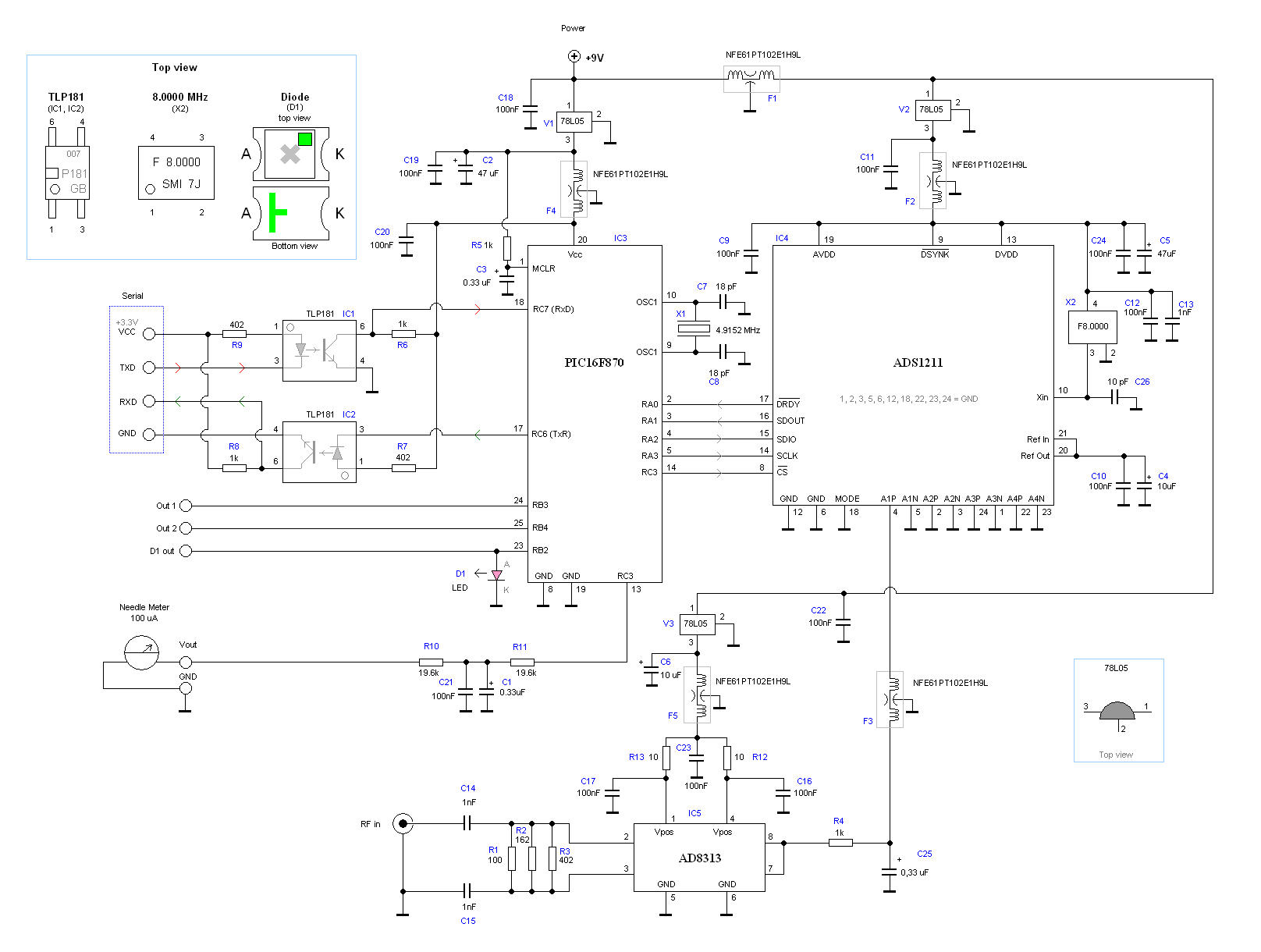
Hardware and schematic
    The main part of this project is a log detector, 24 bit A/D and a PIC16F870
    At the bottom of the schematic you will find IC5 which is a log detector with 70dB dynamic range.
    C14, C15, R1, R2, and R3 forms a 50 ohm input impedance. The log circuit convert the input power into a DC voltage at pin 7, 8.
    The DC voltage is filtered and then enter pin 4 at IC4, which is a 24 bit A/D converter. The A/D runs on a 8 MHz crystal oscillator X2.
    The A/D is very intelligent and has a built in digital filtering system to reject 50/60Hz noise.
    It has also an internal reference system which you can find at pin 20 and 21. The reference voltage is 2.500V
    The A/D has a separate power regulator V2 and filtering F2 to prevent noise.
    When power is applied to the Trinity Meter, the A/D always makes a self calibration and sets the digital filter algorithm.
    The A/D is controlled by a serial interface which is connected to a PIC microcontroller IC3.
    The PIC has a separate power regulator V1 and filtering F4 to prevent noise.

    External gauge meter
    The PIC has a PWM output at pin 13.
    This output is used to drive the external gauge meter, which can be set to follow the virtual gauge meter on the screen.
    A filter consisting of R10 ,R11, C1, C21 filter the PWM into a smooth DC voltage which will not affect the log detector.
    The PWM output (external gauge meter) can be shut off by unchecking the external gauge meter box in main window (more info under software section).
    A 100uA external gauge meter is connected to Vout on PCB. In the windows control software you have a calibration option for the external gauge meter, to adjust max and min levels.
    R10 and R11 (19.6 k ohm) set the max output current to about 128 uA. By changing the R10 and R11 to 1.96k or (2k), the max output current will be 1.28mA. Although, I advice you to use a 100 uA meter.

    The resolution of the external gauge meter is 0.1 uA, so the needle will float in a very smooth movement.

    LED
    At pin 23 a LED D1 is connected. You can either put a smd LED on the PCB or add an external LED. This LED is only for testing purpose.
    Each time power is applied to the Trinity Meter, this LED will blink two times. The indication of the LED will confirm that the PIC and the A/D has woke up and runs properly.
    The first blink indicates that the PIC has woke up and are running, the second blink indicates that the A/D has woke up and are running.
    When the windows software is started and the first data package is sent to the Trinity Meter, the LED D1 will blink one time to indicate that the PIC has received a valid package of data.
    You can now be sure that the PIC receives data from the windows software and that the communication line from the computer through USB and optocoupler is working.
    The LED will not blink for further package of data because I want to keep noise level to a minimum and have as little current spikes as possible. The LED will now sleep.
    To test the LED again, you simply disconnect power and restart the unit.

    Out1 and Out2
    Out1 and Out 2 is digital output from the PIC. These two outputs are not used in this project, but will be used in future project where the Trinity Meter will be used as SWR meter.
    Out1 and Out2 will be used to control a RF switch which switches between forward power and reflected power.
    Although, this is not the project at this time, but it can be good to know that the Trinity Meter is prepared for handling future SWR measurement.

    Serial communication
    The communication between the computer and the Trinity Meter is standard serial RS232.
    Since most computers only have USB connections, I ave choosen to use a USB to TTL module. It is based on the well known CP210x USB controller circuit.
    The output from the USB module is TTL levels (+5V / 0V).
    I have also added an optical barrier between the USB and the Trinity Meter, just to prevent noise and glitches from computer going into the RF meter.

    Two optocoupler separate the communication to and from the computer. In this way I keep noise level to a minimum.
    You can of course use a standard computer Com port with a RS232 to TTL converter as MAX232 if you prefer that.
    Do remember that the input to the Trinity Meter is TTL not RS232 levels (12V and -12V)

    Power supply
    To keep noise level to a minimum I use 9V battery to drive the unit. I have added 3 separate power regulators V1, V2, V3 to the three different sections (log detector, A/D and PIC).
    I have also added lot of bypassing capacitors and several RF filters (F1-F5).
    By isolating the Trinity meter with battery power supply and optical communication, the unit will not be sensitive for external influences.
    Since we have optical isolation, you are free to use as long wires as you wish from the USB unit to the Trinity Meter.

    PCB
    The PCB has been drawn to give minimum noise possible.
    Each part (log amplifier, A/D and PIC) has its own place on the PCB and can be enclosed with RF shielding walls/roof.

    RF input
    The rf input is matched to 50 ohm. In the KIT comes a SMA male connector, which fit to the PCB.
    You can of course solder a 50 ohm coax directly to the input with equal high performance.
    Some prefer N-connectors or BNC connectors. I have several adapters for this purpose. Look under accessories and you will find it.


    Frequency Range and Accuracy
    The accuracy of the Trinity RF Power Meter is very high.
    The error will be max ± 0.2 dB (in 90% of cases the error will be max 0.1 dB).
    The Log Detector is designed to work at 100MHz to 2.5GHz with high linearity and accuracy.
    Althoug, my measurements shows that the AD8313 goes down to 10 MHz with equal high linearity.

    To get high accuracy at 10 MHz, I advice you to calibrate the unit at the desired frequency.

    If you order an assembled Trinity Meter, you will get a file with pre-calibrated data.
    You will also get calibration protocol for several other frequencies going from 10 MHz to 1 GHz.
    Your unit will then be able to measure accurate over the whole frequency range.
    Click here to read more details about the pre-calibrated unit.


    The desoldering wick is a flattened, braided copper sheath Assembly
    The soldering of this unit is pretty basic. I will explain how to assemble this KIT step by step.
    The PCB is a factory manufacture PCB with high quality, which makes the assembly and soldering simple.
    Please do not be scared for soldering smd parts. Smd is not more difficult than hole mounted parts if you use the correct skills and tools.
    Important tools are good light, soldering tool with thin tip, magnifying glasses, tweezers, thin soldering lead, wick impregnated with rosin and calm mind.

    The de-soldering wick is a flattened, braided copper sheath looking like shielding on phono cord (except that the shielding is tinned) without the cord.
    The wick is impregnated with rosin. Place the wick over the legs or bridges of the circuit.
    The wick is then heated by the soldering iron, and the molten solder flows up the braid by capillary action. After that, all bridges will be gone and the circuit looks perfect.
    Thin soldering lead and wick impregnated with rosin are included in the KIT.
    Click here to see photo and read more examples how to solder SOIC and smd components.

    There are ten steps for mounting the parts. Below I describe them with picture and instructions. Some picture can be magnified by clicking onto the picture.

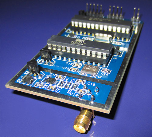
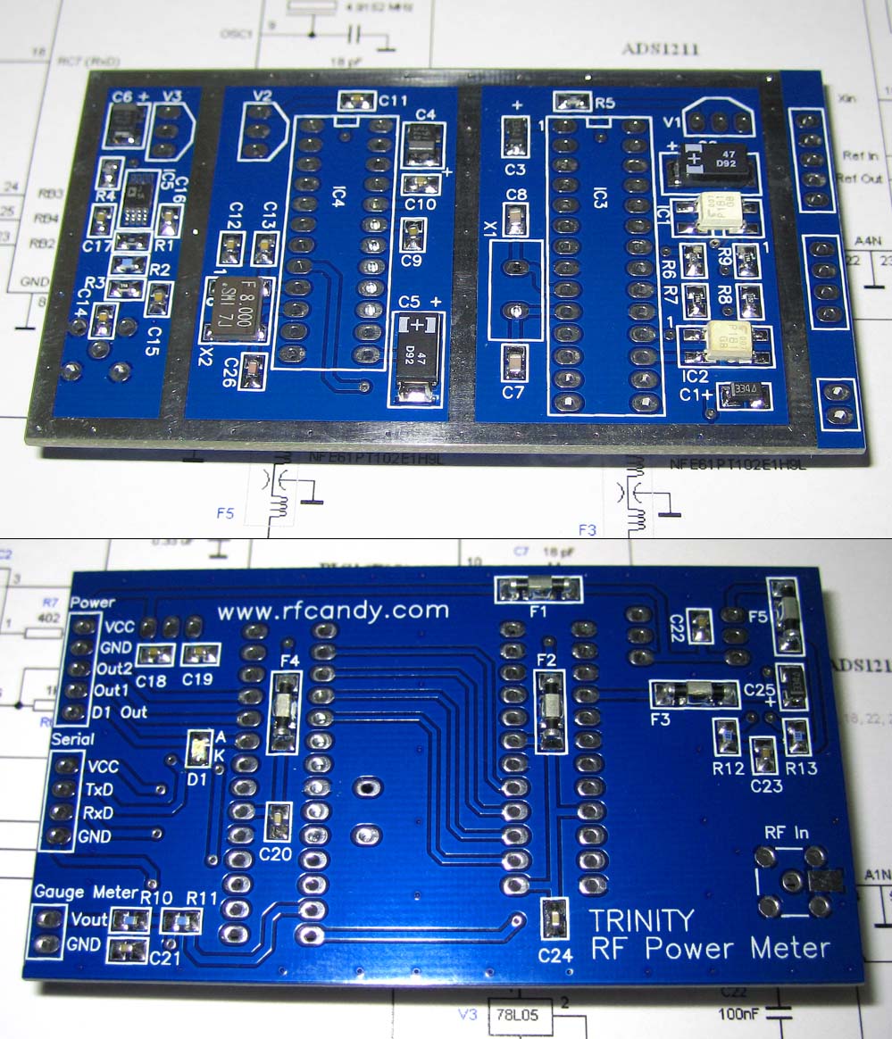
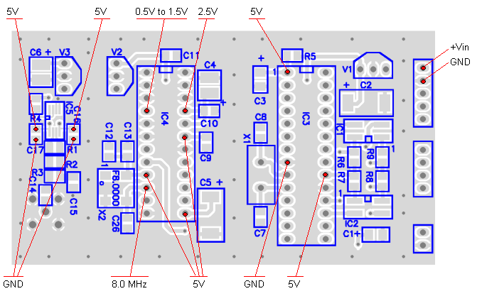
    Top and Bottom layer of the PCB

    Click the image to see full scale image! Click the image to see full scale image!
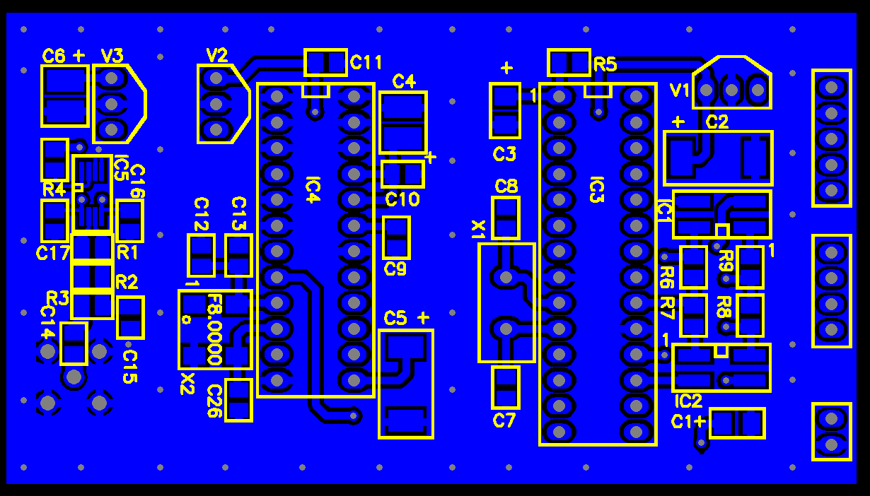
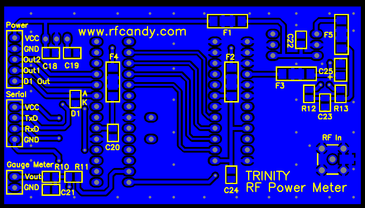
    Click the images to see full scale image!
    1.) IC1, IC2 TLP181
    Place the TLP181 to the PCB as accurate as possible. Magnifying glasses are welcome. Click the picture for more details.
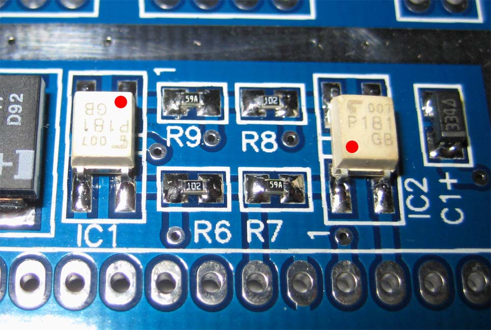
    Make sure that you mount the circuit in correct orientation!
    Place the TLP181 to the PCB and by soldering fixate the top right leg and the bottom left leg. I use a magnifying glass to make sure it is places in line with the PCB pattern.
    From the picture above you can see that the legs are placed in line
    with the PCB pattern, and it looks good.


    2.) IC5 AD8313
    Solder all legs and make sure you have no bridges between legs. Click the picture for more details.
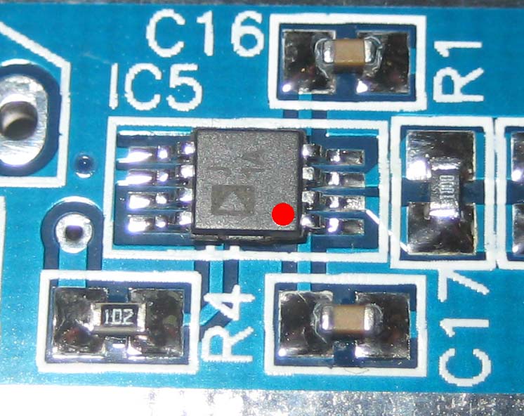
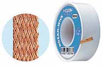
    Make sure that you mount the circuit in correct orientation!
    Place the AD8313 to the PCB and by soldering fixate the top right leg and the bottom left leg. I use a magnifying glass to make sure it is places in line with the PCB pattern. When the corner legs are fixed, solder the rest of the legs. If you get lead bridges between legs, you can easy clean it up by using the wick. Place the wick over the bridges and heat the wick with your soldering tool. The wick will absorb all overflow lead.
    Bridges will be gone and the circuit looks perfect.
    3.) X2 8.000 MHz Crystal
    Solder the crystal, make sure it is oriented correct
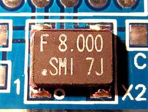
    Make sure that you mount the circuit in correct orientation!

    Place the crystal to the PCB and solder all four pads.
    4.) F1-F5 Ferrite filters
    Solder the ferrite filters

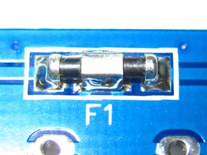
    Solder five ferrite filters as picture show.
    Solder both ends and the middle section.
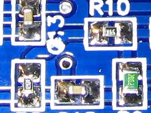
    7.) Capacitor
    Solder all the smd capacitors.  Use a tweezer to hold the smd parts

    Mount smd capacitors below :
  • 10 pF = C26
  • 18 pF = C7, C8
  • 1 nF = C13, C14, C15
  • 100 nF = C9, C10, C11, C12, C16, C17, C18,
    C19, C20, C21, C22, C23, C24
  • 0.33 uF = C1, C3, C25 (White line = positive)
  • 4.7 uF = C4, C6 (White plus = positive)
  • 47 uF = C2, C5 (White plus = positive)

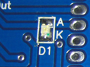
  • 8.) Resistor and LED
    Solder all the smd resistors and the LED.  Use a tweezer to hold the smd parts

    Mount smd resistors below :
  • 10 = R12, R13
  • 100 = R1
  • 162 = R2
  • 402 = R3, R7, R9
  • 1 k = R4, R5, R6, R8
  • 19.6k = R10, R11


  • LED = D1 (green dot is K, see picture above)
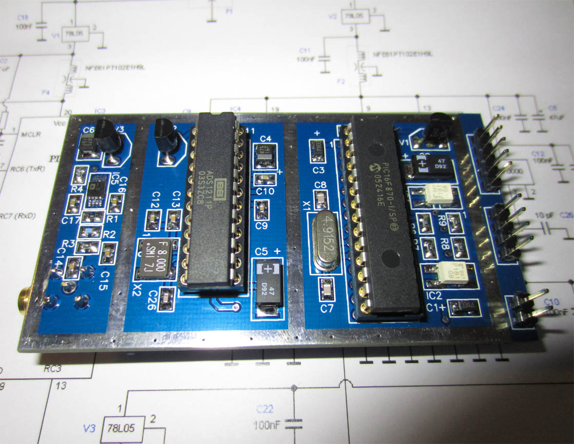
  • 9.) All smd parts mounted
    Click to enlarge !

    At this point all smd parts has been mounted. Click the pic to enlarge.


    10.) Hole mounted parts
    Click to enlarge !

    Mount hole mounted parts below (Click the pic to enlarge):
  • 28 pin IC socket = IC3 (only socket, wait with PIC )
  • 24 pin IC socket = IC4 (only socket, wait with AD )
  • 5 pin Power, 4 pin serial, 2 pin Gauge meter
  • SMA connector(mount on backside of PCB)
  • 78L05 = V1, V2, V3
  • PP3 Connector for 9V battery (Power)
  • USB to TTL converter


  • USB to TTL connection to PCB

    USB to TTL connected to PCB. Click the picture to see larger view.
    The picture above show how to connect the USB to TTL module to the Trinity Meter.
    You need four wires and the connection is simple.
  • Connect the USB +3.3V (red wire) to the the PCB at input VCC.

  • Connect the USB TxD (orange wire) to the the PCB at input TxD.

  • Connect the USB RxD (yellow wire) to the the PCB at input RxD.

  • Connect the USB GND (green wire) to the the PCB at input GND.


  • Testing
    Location of test points

    I advice you to follow this testing procedure to insure correct function before you put the PIC16F870 and ADS1211 into its sockets.
    Perform a visual inspection of the PCB to make sure you have no soldering bridges or misplaced parts. Make sure IC5 (Log Detector) is placed in correct direction.

    Apply about 9V to the PCB at +Vin.
  • Test IC3 power by measure DC voltage from pin 8 (GND) to pin 20. Result should be about +5V.

  • Test IC3 Reset by measure DC voltage from pin 8 (GND) to pin 1. Result should be about +5V.


  • Test IC4 by measure DC voltage from pin 1 (GND) to pin 9, 13 and 19. Result should be about +5V.

  • Test IC4 by measure signal (oscilloscope or equal) from pin 1 (GND) to pin 10 (Xin). Result should be about 8.0 MHz.


  • Test IC5 Power by measure DC voltage over C16 and C17. Result should be about +5V.

  • Test IC5 by measure DC voltage from any (GND) to IC4 pin 4 (A1P). Result should be about 0.5 to 1.0 VDC.

  • This is the voltage from the log amplifier. If a rf signal is applied to the RF input, this voltage will increase.
    (Max testing input power is 0 dBm)

    Disconnect power and put IC3 and IC4 into the sockets, (Make sure you place them in correct direction.)
  • Apply power and control that the LED blinks two times. The first blink should come directly after powerup and the second blink should come after 2-3 seconds.
    Two blink will indicate correct function of the PIC and A/D.

  • The first blink indicate that the PIC has woke up and runs, the second blink indicates that the A/D has woke up and running.
  • Measure the DC voltage on IC4 from pin 1 (GND) to pin 20 (Vref). Result should be about +2.5V.


  • Windows software
    The first thing you must do is to download and unzip the the USB to TTL drivers.
    Below you will be able to download USB to TTL Driver.
    I strongly advice you to follow this 12 steps instruction link how to install the driver properly.
    This driver is a bit old, but works on most computer. Some newer drivers (including the latest) has bugs. This is why I advice you to use the one above.
    The driver will install and setup the CP210x USB to TTL module. You will now have a serial port on your computer.
    You can of course use this serial port for any other purposes as well.

    During the installation process, the USB to TTL module will be assigned a com port number.
    I advice you to follow this 10 steps instruction link how to identify or change Com port number.


    Calibration
    To achieve the high accuracy, the Trinity Meter needs to be calibrated against a well known signal source.
    The calibration data is stored in a file labelled trinity.dat in directly C:\

    When the Trinity software has been installed you do not have a calibration file.
    You can create a calibration file in three ways:

  • Load factory default settings

  • Load Pre-calibrated Data

  • Create your own calibration


  • 1.) Factory Default Settings
    In the main window select Com Port.
    Press button called Calibration in the main window, and the calibration window will appear.
    Press the button labelled Create default calibration.
    Trinity Meter has now default calibration values and the calibration window closes automatically. The Trinity Meter will have about ± 1.5 dB error. The unit is ready to run.
    You only need to this one time!

    Press button called Calibration in the main window, and the calibration window will appear. 
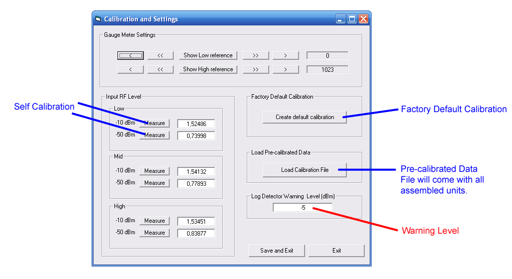
2.) Load Pre-calibrated Data
    In the main window select Com Port.
    If you order an assembled Trinity Meter, you will also receive a pre-calibrated file matching your unit.
    A pre-calibrated Trinity Meter will have max ± 0.2 dB error (in 90% cases the error will be max 0.1 dB).
    The until will be calibrated at 100 MHz (Low), 500 MHz (Mid), 1 GHz (High).
    You will also get calibration protocol for several other frequencies going from 10 MHz to 1 GHz.

    Press button called Calibration in the main window, and the calibration window will appear.
    Press the button labelled Load Calibration File. The window file manager opens and you should select your pre-calibrated file labelled trinity.dat.
    Trinity Meter has now calibration values and the calibration window closes automatically. The unit is ready to run.
    You only need to this one time!

    3.) Self-calibrated unit
    In the main window select Com Port.
    Press button called Calibration in the main window, and the calibration window will appear.
    In the frame Input RF Level, you have three frequency ranges to choose between. Low, Mid and High.
    Start with the Low range (the absolute frequency is not critical but a good rule can be to use the lowest 100Mhz)

  • Apply -10dBm to the Trinity Meter and press the button called Measure -10 dBm. You will now see the A/D measurement in the textbox.

  • Apply -50dBm to the Trinity Meter and press the button called Measure -50 dBm. You will now see the A/D measurement in the textbox.

  • You can also add a 40 dB attenuator and still use -10dBm when calibrating -50 dBm (-10dBm -40dB = -50dBm)

    The Low frequency is now calibrated, change the input frequency to Mid and calibrate the Mid range in the same way.
    Finally change the frequency to High and calibrate the High range in the same way.
    If you know the A/D measurement, you can type them maually as well.
    The three ranges are now calibrated and the unit is ready to run.
    You only need to this one time!

    Do not forget to click Save and Exit button to save your calibration when exit the window.


    Calibration of the external Gauge Meter
    The external Gauge Meter can be calibrated to give min and max scale reading following the virtual gauge meter on the screen.
    Check the checkbox labelled Activate External gauge Meter in the main window.
    Press button called Calibration in the main window, and the calibration window will appear.

    In the top frame Gauge Meter Settings you can click the button Show Low reference and the needle will set to min. (Most often zero is equal to min)
    You can also click the button Show High reference and the needle will set to max.

    You can trim the Low and High references by clicking the arrow buttons.
    When your gauge meter show min and max correct, it will follow the screen gauge meter.
    Do not forget to click Save and Exit button to save your gauge trimming when exit the window.

    Units and Scaling
    The measured RF power will always be displayed in dBm, Watt and Volt.
    The virtual gauge meter can also change unit to display either dBm, Watt or Volt.
    Click the checkbox Screen gauge meter to select which unit you wish to display in the gauge meter.
    The scaling is set by entering Max Scale and Min Scale power. By clicking the checkbox Activate Help Scale, you will get a more detailed scale of the virtual gauge meter.
    You can also change the size of the needle by clicking the checkbox Thin Needle.

    Relative Measurement
    The Trinity meter can measure relative as well.
    Check the checkbox labelled Relative measurement in the main window.
    A frame will appear. Max scale will be set to 20 dB and min scale to 0 dB.
    Press the button Start Measure and you will see the actual measurement (green color).
    By pressing the button Zero Reference, you will set the reference value (yellow colcor).
    Any following measurement will be compared to the zero reference. The gain will be displayed as dB. You can of course change the scale as you wish.
    In the example I have my first measurement at -62.04 dBm and the last measurement is 54.06 dBm, the difference is 7.99 dB.
    I have set the scale to 10 dB as max.

    Trinity Software
    Download Windows Software
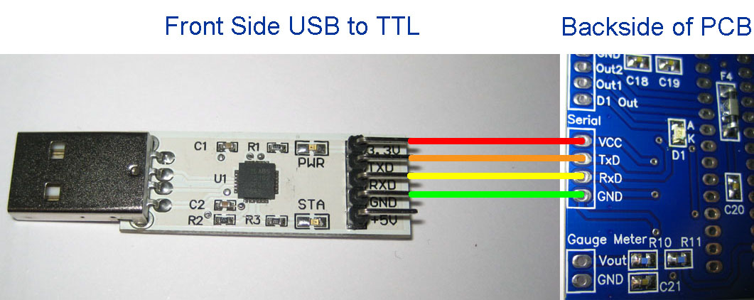
    USB to TLL driver: cp2102driver.zip (171k)

    Trinity Windows software (XP and Win 7): Trinity_Installation.zip (2.99M)

    I advice you to download the Windows software and see how it works on your computer. The software should start up without any problem.
    Although you will not get any measurement until a Trinity Meter is connected to the computer, of course...


    Jim version - Net Trinity Software
    Download Windows Software Net Trinity V2.7
    Net Trinity Windows software : Net_Trinity.rar (1M)

    My good friend Jim from The Netherlands is a very skillfull software engineer.
    He has developed a useful software for the Trinity Meter.

    You can see it at the right and you are free to download it with the link above.

    I hope soon to be able to add a link directly to him,
    mean while you can always e-mail me for questions.


    High Power and Attenuators
    Attenuators comes in many different ways.
    Low power attenuators can be made of smd parts, other use N/BNC/SMA connectors. High power attenuator comes with heat sink.
    As you may understand, the attenuator eats up power and only a fraction of the input power will come out to the output(x dB).
    The rest of the power will end up in heat. Some attenuators can handle higher power (>2W) and they usually have heat sink.

    Attenuation is expressed in decibels of relative power.
    As a rule of thumb 3dB pad halves power, 6dB quarters, 10dB is tenth, 20dB is 100th, 30dB one in one thousand and so on.
    For voltage you double the dBs so for example 6dB is half in voltage.

    Maximum power rating for the log detector circuit is +19dBm, although, the accuracy will start to drop at -5dBm.

    How can I measure stronger signals than -5dBm?
    High power attenuators
    By adding an attenuator you will extend the measure range.
    For example, by adding an attenuator of 10dB, you will be able to measure up to -5dBm + 10dB = +5 dBm with same high accuracy.
    (The measuring range has now extended with 10dB) You can of course add more attenuators and increase the range further.

    If you add 40 dB attenuators, you will be able to measure up to -5dBm +40dB = 35dBm (3.2W).
    If you look in the main window of the Trinity Meter software, you will find a box labelled Attenuation.
    If you use attenators, you enter the amount of attenuation (dB) and the software will always show you correct power reading.

    Another good side effect by using attenuators, is that you will have good impedance matching (50 ohm) towards the measured object,
    becasue the attenuator is purely resistive and minimise any imaginary impedance's.

    Too strong signal
    The Trinity Meter will warn you (Warning box), if the input power exceed critical levels.
    Press button called Calibration in the main window, and the calibration windows will appear.
    In the frame Log Detector Warning level (dBm), you will be able to enter which level the warning will trigg.
    When it comes to AD8313, I advice you to enter -5, because the accuracy will drop if you try to measure stronger signals than -5dBm without attenuator.
    If you need to measure stronger signals, you should add an attenuator and in that way you will keep the high accuracy.
    Although, you can burn the log dectector if the input levels are way too high. If that would happen, you can always replace the log circuit, no worry.

    How to build attenuators
    Attenuators are very simple to build, and they works really good.
    You can make them with resistors. Make sure you do not use wire wounded resistors, they will add inductance, which is bad.

    Here is a good link for calculate attenuators: Pi & Tee Network Resistive Attenuation Calculator

    You can of course always buy professional made attenuators with high accuracy and frequency stability.

    Suggested attenuation vs rf power.

    10dB : Measure up to 0 dBm ( 1 mW)
    20dB : Measure up to +10 dBm ( 10 mW)
    30dB : Measure up to +20 dBm (100 mW)
    40dB : Measure up to +30 dBm ( 1 W )
    50dB : Measure up to +40 dBm ( 10 W )
    60dB : Measure up to +50 dBm (100 W )

    When using attenuators, do NOT forget to add the attenuation value in the main window.

    Good rule of thumb is to start you measurement using too much attenuation rather to little!


    KIT
    Order a KIT
    which will include all parts

    The Trinity RF Power Meter KIT includes all parts, manual, soldering lead, and wick.

    Order here

    Click here to visit the shop


    Accessories for your Trinity RF Power Meters

    In the two links above you will also find accessories for your Trinity RF Power Meter.
    You will find different connectors, adapters, cables, attenuators and more.
    I can supply many different types of connectors and adapters, so if you have special demands, please e-mail me.


    Trouble Shooting section
    If you have a problem with your unit, you might find this section helpful.
    let's fix this
  • The LED does not blink after power up.

  • Make sure you have connected the LED in the correct direction.
    A simple way to test the LED is to connect a resistor of 330 ohm between pin 20 and pin 13 of IC3 (PIC).
    The LED should give constant light.

    Make sure you have +5V to pin 20 of the PIC.
    You should test that the Reset (pin 1) goes high when power is turned on.
    Put the PIC (IC3) into its socket and apply power. Make sure you have placed it in correct direction.
    The oscillator should be running at 4.9152 MHz. (Test with oscilloscope or equal equipment)
    The LED should blink one time to verify that the PIC is running.

  • The LED does not blink two times

  • Check that the A/D circuit (IC4) s placed in correct way.
    Check that you do not have any soldering bridges between legs or to ground.
    Check that you have 8.00 MHz signal into pin 10 (Xin).
    Check that you have 2.50V at reference output pin 20 and 21.

  • My RS232 computer communication is not working!

  • Make sure the optocouplers IC1 and IC2 is mounted in correct direction.
    Make sure you that you have installed the USB to TTL Module correct.
    Make sure you that you have chosen correct comport.
    Power up Trinity and start the windows application. Choose comport and start to measure.
    The first data package sent to the Trinity Meter will make the LED blink one time. If the LED blinks one time, you can be sure that the Trinity Meter has received a valid data package.
    The Trinity Meter will then respond with a package.
    You can of course monitor this RS232 communication with oscilloscope or equal.
    Pin 17 and 18 on the PIC (IC3) is the output and input for communication.

    You can test IC2 by removing IC3 (PIC16F870) and measure the current from pin 17 to ground.
    The current should be about 8-12mA. At the same time the voltage from GND (serial) to RxD (serial) should go low.
    When the current measurement from pin 17 to ground is broken the voltage from GND (serial) to RxD (serial) should go back up to 3.3V

  • I have no power reading?

  • Make sure that IC5 is mounted in correct direction.
    Test IC5 by measure DC voltage from any (GND) to IC4 pin 4 (A1P). Result Should be about 0.5 to 1.0 VDC.

    If you have any problems, you are always welcome to e-mail and I guarantee we will fix it.

    Final word
    I hope you have enjoyed reading about this Power meter project.
    Hopefully you have found new inspiration for your own projects.
    The main reason I constructed this power meter was my own need of a high quality instrument.

    Gallery

    Picture gallery of Trinity RF Power Meter. Click the picture to see larger views.

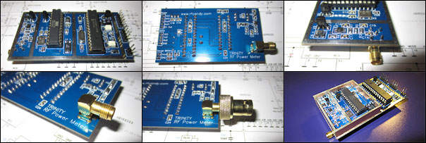
    Click the picture above to see the picture gallery.


    Back to main Page  |  Contact Me  |  Cheap components

    Copyright © Last modified on 30 dec 2011.